147th ASA Meeting, New York, NY
Sound
Detection Based on Tunneling Electrons
Dr. Michael Pedersen- pedersen@mems-exchange.org
The MEMS Exchange/CNRI
1895 Preston White Drive, Ste. 100
Reston, VA 20191
USA
Popular version of paper 4aEA2
Presented Thursday morning, May 27, 2004
147th ASA Meeting, New York, NY
In this paper we discuss the possibility of building a microphone with revolutionary sensitivity, in which the detection mechanism is based on one of the tiniest physical effects in nature, known as electron surface tunneling. Electron surface tunneling is a well known phenomenon, which is predicted by quantum mechanical theory, and is exploited in surface tunneling microscopes (STM) capable of distinguishing individual atoms on surfaces.
What
is electron surface tunneling?
The quantum theory of surface tunneling focuses on the possibility that
an electron can jump from the electron cloud on the surface of one
material to an electron cloud on the surface of another material. The
important thing here is that the two materials are physically separated
by a (forbidden) region in which free electrons are not allowed to
exist. Examples of materials for such a forbidden region are electrical
insulators, vacuum, and even air. An analogy to think of is a person
trapped in an underwater cave. To escape the cave, the person must swim
under water out of the cave. In this case the water is the forbidden
region, because a person can only hold his or her breath for a given
period. The same applies to the electron. It can only survive for a very
short time in the forbidden region. If the electron makes it across the
region, we say that it has tunneled through the region.
A basic experiment which demonstrates surface tunneling is shown in
figure 1. In this experiment we have a conducting surface and a
conducting tip, which we bring in very close proximity of the surface.
An electric potential is applied between the tip and surface, which
creates a potential difference across the forbidden region.
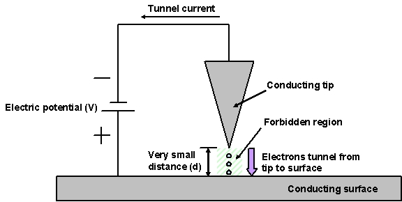
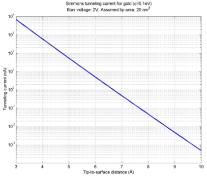
Figure 1 (left) and 2 (right):
Basic surface tunneling experiment and approximate
tunnel current vs. tip-to-surface distance for a gold tip and surface.
The potential difference helps increase the chance that an electron in the
tip can make the jump to the surface. The tunneling of the electrons gives rise
to an electrical current between the tip and surface (the tunnel current). To
explain what is happening in this experiment one must use quantum theory to
find wave function solutions that satisfy Schrödinger's equation with the
boundary conditions for the three regions (tip, forbidden region, surface).
If we use the Wentzel, Kramer, and Brillouin (WKB) approximation, which makes
certain simplified assumptions about the wave function solutions, and if we
further assume that the tip and surface are made of the same material, and that
the electrons are distributed according to the Fermi statistics, we can use
Simmons formalism to derive a tunnel current density given by:
(1) 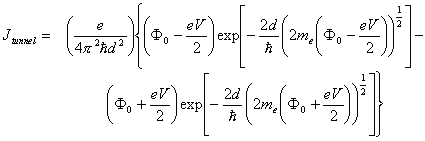 .
.
It is important to realize from equation (1) that there is an exponential dependence
between the tunneling current and the distance of the tip to the surface. Therefore
even minute changes in distance will lead to a significant change in tunnel
current. In figure 2 the dependence of the tunneling current on the distance
is shown for a gold tip and surface with an electrical potential of 2 V and
an assumed tip area of 20 nm^2. As we can see, the tip must be brought very
close to the surface to achieve a measurable tunnel current, however even a
change of distance of 1 Å (less than half the diameter of an atom) will
change the tunneling current by a factor 10.
Bringing the tip this close to the surface, and maintaining its distance without touching the surface presents a tremendous control problem. A large scale analogy to think of is to drive your car at 60 mph up to a wall and stopping without hitting the wall such that the bumper is less than 0.1" from the wall. With the use of micro electro mechanical systems (MEMS) technology, it has become possible to realize very sharp tips attached to a suspension cantilever with built in actuators, that can move the tip with extremely small amplitudes (figure 3). The tip and cantilever are normally attached to a larger structure that can be moved with conventional actuators to bring the tip within ~1 micron of the surface (~2000 times larger than the needed distance). The actuators on the cantilever are then engaged, while constantly monitoring the tunnel current, until the specified tunnel current is achieved.
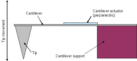
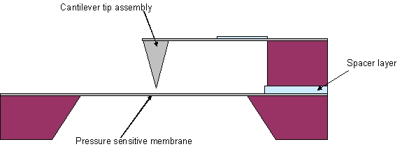
Figure 3 (left) and 4 (right): Basic structure of cantilever
suspended tunneling tip and structure of electron tunneling microphone.
How
would an electron tunneling microphone work?
A simple approach to realize a microphone using such a tunneling tip is
shown in figure 4. In this case we use MEMS technology to fabricate a
sensitive membrane, which will deflect due to an acoustic sound
pressure. By using MEMS technology for the assembly, we can realize a
structure with <1 micron initial distance between the membrane and
the tip, which means only the cantilever actuators are needed to control
the tip movement. The control circuit of the actuator is used in a
feedback loop to maintain a certain tunnel current, and as the membrane
deflects, the actuator signal is changed to maintain the tunnel current
and hence the tip distance. The actuator signal therefore becomes the
microphone output signal.
There are a number of problems with this basic structure. Firstly,
the fabrication of such a MEMS structure would be very complicated and
difficult to realize. The result would be that the cost of the device
would be exceedingly high when compared to other microphone
technologies. Secondly, the cantilever will have a significant
sensitivity to vibration, due to its inertial mass, which will manifest
itself as an artifact in the microphone signal. The vibration
sensitivity will be much higher for this structure than other comparable
microphone structures based on other detection methods (i.e.
piezoelectric or capacitive). In addition, the resonance frequency of
the cantilever tip is bound to fall within the frequency range of
interest in the microphone, which will make control of the tip
deflection extremely difficult or impossible.
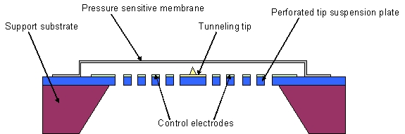
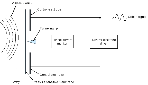
Figure 5 (left) and 6 (right): A new electron tunneling microphone
structure and basic control circuit needed for electron tunneling microphone.
Our new better approach is shown in figure 5. In this case, we have
turned the tunneling structure upside down, and we have integrated the
tip into a single monolithic structure. An important difference here is
that the tip is now mounted on a rigid perforated suspension plate. As
a result the vibration sensitivity of the microphone has been reduced
to that of the thin flexible membrane (similar to other comparable
microphone structures). Also included on the suspension plate are
control electrodes, which are used to move the conductive membrane into
close proximity of the tunneling tip using electrostatic attraction.
Another important difference is that in the structure in figure 4, the cantilever
tip would be controlled to move with the membrane as it deflects in response
to an acoustic wave. In the structure in figure 5, the membrane is controlled
directly to remain in a fixed location. In other words, the membrane in figure
5 will not move in response to a sound pressure, but instead the electrical
control potential will change to maintain the position of the membrane. A basic
block diagram of the circuit needed to achieve this is shown in figure 6. The
tunnel current monitor includes an internal current reference, to which the
tunnel current is compared. The error signal of this comparison is amplified
and fed to the control electrode driver, which closes the feedback loop by driving
the control electrodes and hence moving the membrane. First order calculations
indicate that revolutionary microphone sensitivities >200 mV/Pa can be achieved
with membranes smaller than 0.5 x 0.5 mm.