
Joung-Woo Choi - jwoo@kaist.ac.kr
Yang-Hann Kim - yanghannkim@kaist.ac.kr
Center for Noise and Vibration Control (NOVIC)
Korea Advanced Institute of Science and Technology (KAIST)
Science Town
Daejeon, Korea
Popular version of paper 3aSP10
Presented Wednesday morning, October 19, 2005
ASA/NOISE-CON 2005 Meeting, Minneapolis, MN
 Where do you like to sit in a
concert hall? Nobody prefers to sit in the corner seat. This is not only because
your viewing angle is contorted, but also because the sound that reaches you
is more likely to be distorted. As you may have experienced in many listening
environments, sound quality is not uniform from every seat in a hall. This had
motivated us to develop techniques for controlling the sound in a selected region
of a listening space.
Where do you like to sit in a
concert hall? Nobody prefers to sit in the corner seat. This is not only because
your viewing angle is contorted, but also because the sound that reaches you
is more likely to be distorted. As you may have experienced in many listening
environments, sound quality is not uniform from every seat in a hall. This had
motivated us to develop techniques for controlling the sound in a selected region
of a listening space.
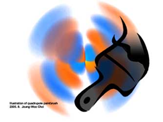
Controlling sound in a selected area is somewhat analogous to painting a picture on a selected canvas. Imagine that you are drawing a sound picture in space. Your listening position is now your canvas, which generates the shape and color of sound according to the touch of your acoustic paintbrushes.
How can we actually paint a sound picture in the listening room? A fundamental
way to paint a picture is to make strokes. If you think of those strokes as
sound fields from loudspeakers, then we can mix and overlap the sound strokes
together by playing multiple loudspeakers simultaneously. In fact, the interference
of the sound fields of the loudspeaker array is the key tenet of sound painting.
Using the interference effect of multiple loudspeakers, researchers have sought
to make various sound pictures. For example, we can make a photocopy of a symphony
hall's sound picture. This kind of technique has been known as sound field reproduction.
However, copying an existing sound picture is not always satisfactory, because
people often want to draw their own picture.
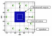
There are various ways to paint a picture. Among them, we attempt to introduce two different drawing techniques. The primary focus of the developed technique has to do with the brightness and contrast of acoustic image. In essence, the acoustic brightness control seeks a way to enhance loudness of sound over a chosen area. The technology that enables the brightness control is somewhat related to that of active sonar, which generates a sharply focused sound beam to find a target. But the brightness control differs from the technique in that we can lighten a selected area instead of a point. On the other hand, the contrast control aims to enhance the difference in loudness between two neighboring regions. This enables us to make two different kinds of zones - a zone of quiet and a zone of loud sound - at the same time. The next figure illustrates how the methods can draw acoustic brightness and contrast in space. To simulate this painting, 17 speakers are modeled and controlled. There are interesting areas that have mediocre brightness. It is noteworthy that these areas disappear when we enhance the acoustic contrast.
The brightness and contrast control is rather static concept. In fact, these have nothing to do with the movement of pictures. If we move or draw a wavefront within a selected area, then the listener in the area would also feel the movement of sound. To explain the principle of the wavefront control, one should understand that any sound field can be broken down into many planar (flat) wave fronts propagating in various directions. If we can focus the sound energy only on the wave components propagating in a desired direction, then the propagating direction of the wavefront would be aligned in the desired direction. We can then utilize the acoustic brightness or contrast control again, in order to focus the sound. The only difference is in that we focus sound energy on a wave component rather than an area.
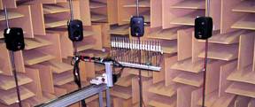
What is shown above is an example of the wavefront control system. Twelve loudspeakers were distributed in a circular shape, and the sound field was controlled to propagate in 225 degree direction (corresponding to the southwest direction). The sound fields generated from the controlled system at different frequency bands are presented below. These animations show the instantaneous pressure change in space and time with a direction of propagation that is aligned in a desired direction.
|
(a) 250Hz band (download) |
(b) 500Hz band (download) |
(c) 1kHz band (download) |
The painting techniques presented in here are just a few examples. However, based on these approaches, we are expecting you to be able to paint your own sound picture at home in the near future.