
Two Healthcare Buildings Get the Power,
the Noise, and the Vibration from a Gas Turbine Generator System
Chad Himmel - himmel@jeacoustics.com
JEAcoustics
1705 W Koenig Ln
Austin, TX 78756
Popular version of paper 2aNSc10
Presented Tuesday morning, April 20, 2010
159th ASA Meeting, Baltimore, MD
An innovative municipal utility in Austin, Texas, built an efficient small power plant on the site of an urban redevelopment area. The plant is adjacent to a new childrens hospital and a medical office building.
Inside that plant is a 4.3-megawatt natural gas turbine and a heat-recovery steam generator, plus electrical and absorption chillers, among other equipment. The facility operates as a highly efficient cogeneration plant, 75% more efficient than coal-fired plants. It provides power directly to the hospital and is linked to the municipal grid to export power to the main utility and its 380,000 customers. It is capable of providing all the hospitals power, air conditioning, water, and steam needs. A chilled water trunk line in a district cooling loop provides air conditioning to other buildings in the development area.
When the turbine was first fired up in 2007, noise emanating from the plant was quite noticeably loud and tonal, raising immediate concerns about the noise that might be received inside medical offices directly across a 50-foot wide driveway. Investigations confirmed the turbine generator system was the primary source of that noise, which radiated from the enclosure casing and various air inlet and discharge openings with a strong tone around 90 decibels at 250 Hz. Investigations also found dominant ground borne vibration in the vicinity of the turbine, with strong tonal peaks relating to turbine and generator rotational rates. It turned out that part of the standard installation of the turbine package was missing. The under-floor base of the turbine enclosure contains some of the systems piping and ancillary parts, and the remainder of that floor cavity was supposed to be filled with grout to complete the installation on site. After grout was added to that floor cavity, there was a significant reduction of airborne noise radiated from the casing. The tonal noise at 250 Hz was reduced by 16 decibels, eliminating concerns for noise reaching the nearby medical office building. Ground borne vibration near the plant was not affected much by the addition of the grout filling.
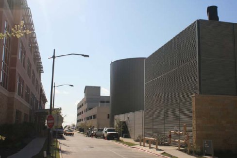
Figure 1. Power plant (right) and medical office building (left).
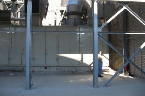
Figure 2. Gas turbine generator enclosure inside the plant. The grout-filled floor cavity is in the portion below the door panels.
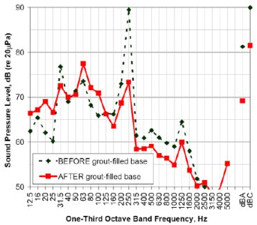
Figure 3. The sound spectrum of plant noise (Leq, or equivalent average for a duration of about one or two minutes) measured near the medical building before and after the turbine enclosure floor cavity was filled with grout.
About 500 feet down the road at the childrens hospital, a new neurosurgery suite addition would include an intra-operative magnetic resonance imaging (MRI) unit. MRI systems are subject to potential image distortion, experiencing reduced image quality if there is enough building vibration shaking the magnet. Ambient vibration measurements at that site before construction indicated there were prominent frequencies of disturbance that could affect MRI image quality. Vibration measurements near the turbine showed matching strong tonal peaks.
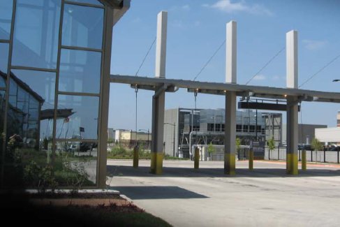
Figure 4. View towards the power plant (center) from the location of the proposed MRI addition before it was built.
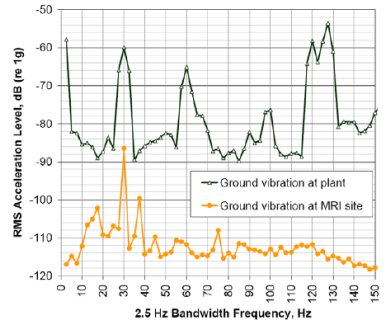
Figure 5. Ground borne vibration (Leq) measured on concrete pavement near the turbine and at the proposed new MRI location.
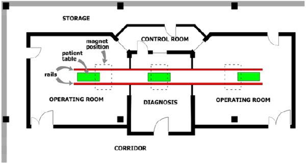
Figure 6. Schematic floor plan of the intra-operative MRI suite.
An intra-operative type of MRI unit is capable of moving the magnet back and forth along a rail system into separate rooms within an MRI suite. The magnet is typically suspended on structural steel rails above the floor, and the patient tables in imaging rooms are floor-mounted. In this case, moving the magnet to three different patient tables could allow one magnet to be used for diagnosis in the center room or moved to surgery in one of two operating rooms.
The new MRI building addition would be mostly underground. For design of the addition, we asked structural engineers to review elements in their design for probable structural resonant frequencies. We wanted them to avoid those resonant frequencies that would be divisors or multiples of 30 Hz, such as 7.5 Hz, 15 Hz, or 60 Hz. The purpose was to avoid matching the turbines 30-Hz harmonic disturbances, so that the building structure would not be easily energized by the turbines prominent ground borne energy. This condition was most relevant in floors where patient table pedestals were to be mounted and where columns and beams would support the magnet rails.
We also asked structural engineers to install a resilient drainage matrix on the outer vertical surfaces of the underground walls before backfilling. The purpose was to hold soil away from the walls to reduce the impact of the strong 30-Hz vibration signal in the ground on side walls of the underground structure.
We have been told the turbine is currently not operating but will be running again once installation is complete on a replacement turbine that is going to go inside the existing turbine generator enclosure. That means post-construction vibration results for the MRI facility are not available at this time, but we hope to conduct measurements to confirm post-construction conditions at the hospitals MRI addition soonpossibly in time for presentation on April 20.
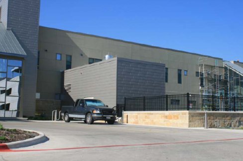
Figure 7. The location of new underground MRI addition after construction. The roof of the addition with fence railing on top is in the foreground (center right).