Philip J. Morris – pjm@psu.edu
Dennis K. McLaughlin – dkm2@psu.edu
Michael B. Lurie – mbl160@psu.edu
Alex M. Karns – amk5432@psu.edu
Penn State University
229 Hammond Building
University Park, PA 16802
Popular version of paper 3aPAa2
Presented Wednesday morning, December 4, 2013
166th ASA Meeting, San Francisco
The annual cost of benefits paid to veterans for hearing-related disabilities by the Veterans Administration is more than a billion dollars and is increasing rapidly. For Navy personnel a significant cause of hearing loss is the engine noise from tactical aircraft. This is especially the case for aircraft carrier deck personnel.
The two main sources of engine noise for the low bypass ratio turbofan engines used by tactical aircraft are broadband shock-associated noise and jet mixing noise. The former is generated by the passage of turbulent eddies through the shock cell structure in the jet exhaust. This shock structure, which can be seen as a diamond pattern in pictures of fighter aircraft at night, is caused by the mismatch between the pressure at the jet exit and the surrounding air. Broadband shock-associated noise dominates the noise to the side of the engine and towards the nose of the aircraft. Mixing noise has the highest levels and is radiated behind the aircraft. The sound is generated by large turbulent eddies in the jet exhaust that are traveling supersonically relative to the speed of sound in the surrounding air. Even with hearing protection involving special helmets and earplugs, the levels of noise are sufficient to cause hearing damage.
Many devices and designs have been developed to reduce jet engine noise. These have been particularly successful for commercial aircraft engines. The use of high bypass ratio turbofan engines and the use of chevrons - the serrations on the fan exhaust - are now a common sight on the newer commercial aircraft. But these engines operate with exhaust velocities that are generally subsonic and though chevrons can play a role in noise reduction for tactical fighter aircraft engines, other strategies for noise reduction are needed.
One successful technique for noise reduction at take-off conditions is the use of corrugated seals in the diverging section of the jet nozzle [1]. The nozzle in a tactical aircraft engine has a convergent-divergent shape. First the nozzle area decreases until it reaches the minimum area location, called the throat, and then the area increases until the nozzle exit is reached. To allow the ratio of the exit area to the throat area to vary, the divergent section of the nozzle is made up of interleaving flaps and seals. The corrugated seals replace the conventional flat seals. The shape of a corrugated seal is carefully designed and has a very low profile near the throat and increases in height and width up to the nozzle exit. The cross section looks like an inverted "U". The seals work in two ways to reduce the jet noise. Firstly they effectively change the nozzle area ratio which reduces the shock cell strength and hence the shock-associated noise. At the same time, streamwise vortices are generated along the sides of the corrugations, and these enhance the mixing in the jet exhaust. This breaks up the large eddies and reduces their radiation efficiency. But the problem with the original corrugated seal design is that it produces a performance loss when the aircraft is flying at altitude.
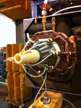
To overcome this problem, researchers at Penn State University, with support from the Office of Naval Research, have developed a fluidic version of the corrugated seals. They are called "fluidic inserts" [2]. These corrugations are generated by injecting air through the nozzle diverging section walls. The pressures and mass flow rates of the injectors are selected to be practically achievable on a full scale engine. Experiments have been conducted in an anechoic facility on a small-scale nozzle. Fig. 1 is a photograph of the model exhaust nozzle outfitted with the distributed blowing system. Fig. 2 shows the same arrangement with the nozzle fairing added to provide smooth flow around the jet when experiments are conducted with the simulated forward stream.
Fig. #1: Model exhaust nozzle with distributed blowing system.
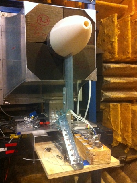
Fig. #2: Nozzle with aerodynamic fairing.
Both noise measurements and flow visualizations have been performed. Noise reductions of more than 5 dB (a sixty percent reduction in the sound pressure) have been measured in the peak noise direction and the broadband shock-associated noise is effectively eliminated. The significant advantage of the fluidic inserts is that they can be adjusted or turned off depending on the operating conditions of the engine. Fig. 3 shows the result of measurements from an array of microphones in the far field of an over-expanded jet operating with and without the distributed blowing system. The left panel shows spectra at five polar positions in the far field comparing the baseline nozzle jet with a jet with fluidic inserts observed at two azimuthal angles, in line with and between the injectors. The right-hand panel shows the difference between the overall sound pressure level (OASPL) for the two azimuthal alignment positions of the microphone array. The total injection mass flow rate for these measurements was less than four percent of the nozzle core mass flow rate.
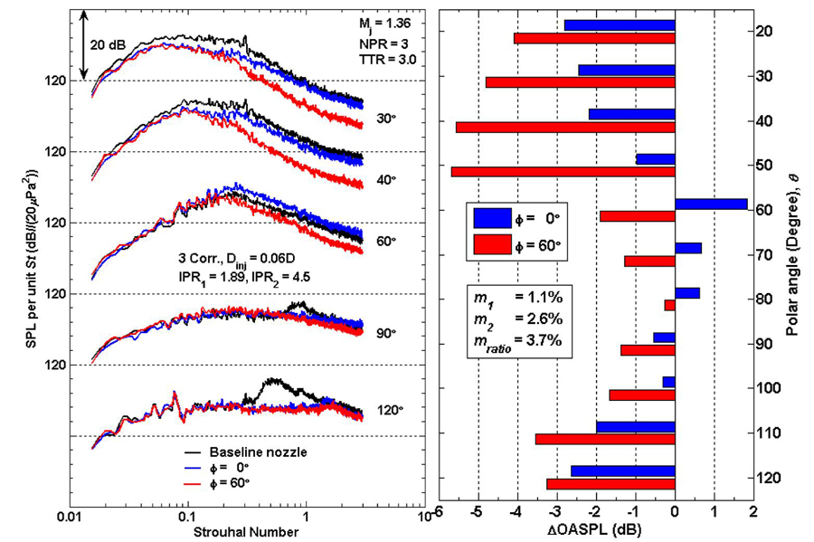
Fig. #3: Acoustic measurement results, spectra and OASPL, for a design Mach number jet Md = 1.65, with Dinj = 1.32 mm or 0.06 Djet).
To assist in the design and understanding of the fluidic inserts, numerical simulations of the nozzle and jet exhaust are being conducted. This includes an examination of the effects of different injector pressures and mass flow rates. Comparisons of the simulations with flow measurements have shown good agreement. The simulations are also being used to identify flow characteristics that can be used to indicate the best noise reductions. These characteristics can then be the target for future designs. Fig. 4 shows contours of equal temperature inside the nozzle in a plane passing through one fluidic insert. The injected air is unheated, so it is shown in blue. It can be seen how the fluidic insert deflects the flow in the same manner as would a solid corrugation.
Fig. #4: Simulated contours of static temperature on cross section through one fluidic insert. The cold injected air is shown in blue, and the deflection of the hot core flow can be seen in red and yellow.
The researchers are currently examining different injector designs. In addition, the model jet is being placed in a moving stream to determine if the fluidic inserts give the same noise reductions when the aircraft is in flight. Support is also being provided by the Office of Naval Research to increase the scale of the nozzle. Noise tests will be conducted in cooperation with General Electric Aviation.
References:
[1] Seiner, J. M., Jansen, B. J. and Murray, N., "Aero-performance efficient noise suppression of a supersonic model twin jet nacelle," AIAA Paper 2009-3130, 2009.
[2] Morris, P. J., McLaughlin, D. K. and Kuo, C.-W., "Noise Reduction in Supersonic Jets by Nozzle Fluidic Inserts," Journal of Sound and Vibration, 332, 2013, pp. 3992-4003.