2aSPa8 and 4aSP6 – Safe and Sound – Using acoustics to improve the safety of autonomous vehicles

Eoin A King – eoking@hartford.edu
Akin Tatoglu
Digno Iglesias
Anthony Matriss
Ethan Wagner

Department of Mechanical Engineering
University of Hartford
200 Bloomfield Avenue
West Hartford, CT 06117

Popular version of papers 2aSPa8 and 4aSP6
Presented Tuesday and Thursday morning, May 14 & 16, 2019
177th ASA Meeting, Louisville, KY

Introduction
In cities across the world everyday, people use and process acoustic alerts to safely interact in and amongst traffic; drivers listen for emergency sirens from police cars or fire engines, or the sounding of a horn to warn of an impending collision, while pedestrians listen for cars when crossing a road – a city is full of sounds with meaning, and these sounds make the city a safer place.

Future cities will see the large-scale deployment of (semi-) autonomous vehicles (AVs). AV technology is quickly becoming a reality, however, the manner in which AVs and other vehicles will coexist and communicate with one another is still unclear, especially during the prolonged period of mixed vehicles sharing the road. In particular, the manner in which Autonomous Vehicles can use acoustic cues to supplement their decision-making process is an area that needs development.

The research presented here aims to identify the meaning behind specific sounds in a city related to safety. We are developing methodologies to recognize and locate acoustic alerts in cities and use this information to inform the decision-making process of all road users, with particular emphasis on Autonomous Vehicles. Initially we aim to define a new set of audio-visual detection and localization tools to identify the location of a rapidly approaching emergency vehicle. In short we are trying to develop the ‘ears’ to complement the ‘eyes’ already present on autonomous vehicles.

Test Set-Up
For our initial tests we developed a low cost array consisting of two linear arrays of 4 MEMS microphones. The array was used in conjunction with a mobile robot equipped with visual sensors as shown in Fig. 1. Our array acquired acoustic signals that were analyzed to i) identify the presence of an emergency siren, and then ii) determine the location of the sound source (which was occasionally behind an obstacle). Initially our tests were conducted in the controlled setting of an anechoic chamber.

autonomous vehicles

Picture 1: Test Robot with Acoustic Array

Step 1: Using convolutional neural networks for the detection of an emergency siren
Using advanced machine learning techniques, it has become possible to ‘teach’ a machine (or a vehicle) to recognize certain sounds. We used a deep layer Convolutional Neural Network (CNN) and trained it to recognize emergency sirens in real time, with 99.5% accuracy in test audio signals.

Step 2: Identifying the location of the source of the emergency siren
Once an emergency sound has been detected, it must be rapidly localized. This is a complex task in a city environment, due to moving sources, reflections from buildings, other noise sources, etc. However, by combining acoustic results with information acquired from the visual sensors already present on an autonomous vehicle, it will be possible to identify the location of a sound source. In our research, we modified an existing direction-of-arrival algorithm to report a number of sound source directions, arising from multiple reflections in the environment (i.e. every reflection is recognized as an individual source). These results can be combined with the 3D map of the area acquired from the robot’s visual sensors. A reverse ray tracing approach can then be used to triangulate the likely position of the source.

Picture 2: Example test results. Note in this test our array indicates a source at approximately 30o and another at approximately -60o.

Picture 3: Ray Trace Method. Note, by tracing the path of the estimated angles, both reflected and direct, the approximate source location can be triangulated.

Video explaining theory.

4aSP4 – Streaming Video through Biological Tissues using Ultrasonic Communication

Gizem Tabak – tabak2@illinois.edu
Michael Oelze – oelze@illinois.edu
Andrew Singer – acsinger@illinois.edu
University of Illinois at Urbana-Champaign
306 N Wright St
Urbana, IL 61801

Popular version of paper 4aSP4
Presented Thursday morning, May 16, 2019
177th ASA Meeting, Louisville, KY

Researchers at the University of Illinois at Urbana-Champaign have developed a fast, wireless communication alternative that also has biomedical implications. Instead of using radio frequency (RF) to transmit signals, the team is using ultrasonic waves to send signals at high enough data rates to transmit video through animal or human tissue.

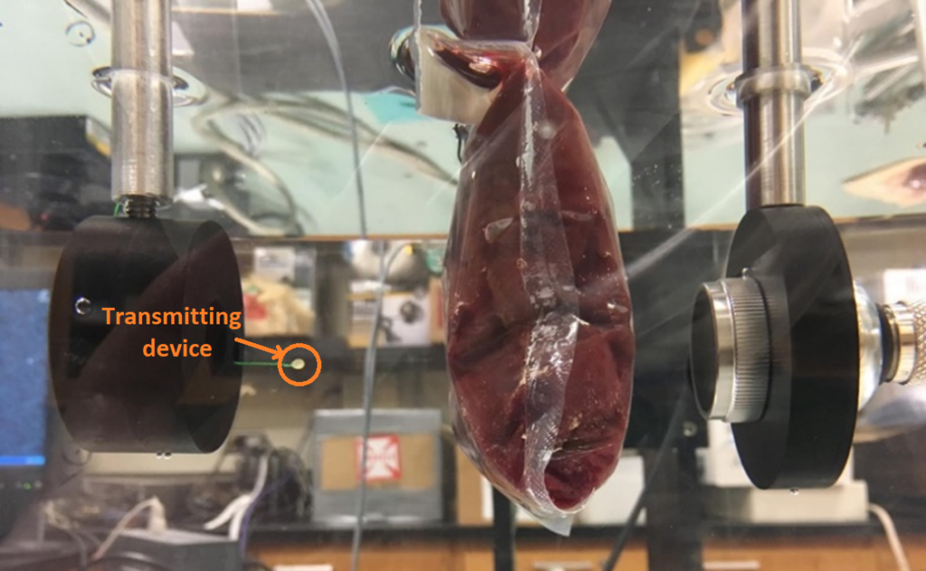
The team of electrical and computer engineering professors Andrew Singer and Michael Oelze and graduate researcher Gizem Tabak have achieved a transmission rate of 4 megabits per second through animal tissue with 2-mm transmitting devices. This rate is high enough to send high definition video (3 Mbps) and 15 times faster than that RF waves can currently deliver.

ultrasonic communication

Figure 1 – Experimental setup for streaming at 4Mbps through 2” beef liver

The team is using this approach for communicating with implanted medical devices, like those used to scan tissue in a patients’ gastrointestinal (GI) tract.

Currently one of two methods are used to image the GI tract. The first is video endoscopy, which involves inserting a long probe with a camera and light down the throat to take real-time video and send it to an attached computer. This method has limitations in that it cannot reach the midsection of the GI tract and is highly invasive.

The second method involves a patient swallowing a pill that contains a mini camera that can take images throughout the tract. After a day or so, the pill is retrieved, and the physician can extract the images. This method, however, is entirely offline, meaning there is no real-time interaction with the camera inside the patient.

A third option uses the camera pill approach but sends the images through RF waves, which are absorbed by the surrounding tissue. Due to safety regulations governing electromagnetic radiation, the transmitted signal power is limited, resulting in data rates of only 267 kilobits per second.

The Illinois team is proposing to use ultrasound, a method that has already proven safe for medical imaging, as a communication method. Having achieved data rates of 4 Mbps with this system through animal tissue, the team is translating the approach to operate in real-time for use in the human body.

Pairing this communication technology with the camera pill approach, the device not only could send real-time video, but also could be remotely controlled. For example, it might travel to specific areas and rotate to arbitrary orientations. It may even be possible to take tissue samples for biopsy, essentially replacing endoscopic procedures or surgeries through such mini-remote controlled robotic devices.

1aSP1 – From Paper Cranes to New Tech Gains: Frequency Tuning through Origami Folding

Kazuko Fuchi – kfuchi1@udayton.edu
University of Dayton Research Institute
300 College Park, Dayton, OH 45469

Andrew Gillman – andrew.gillman.1.ctr@us.af.mil
Alexander Pankonien – alexander.pankonien.1@us.af.mil
Philip Buskohl – philip.buskohl.1@us.af.mil
Air Force Research Laboratory
Wright-Patterson Air Force Base, OH 45433

Deanna Sessions – deanna.sessions@psu.edu
Gregory Huff – ghuff@psu.edu
Department of Electrical Engineering and Computer Science
Penn State University
207 Electrical Engineering West, University Park, PA 16802

Popular version of lecture: 1aSP1 Topology optimization of origami-inspired reconfigurable frequency selective surfaces
Presented Monday morning, 9:00 AM – 11:15 AM, May 13, 2019
177th ASA Meeting, Louisville, Kentucky

The use of mathematics and computer algorithms by origami artists has led to a renaissance of the art of origami in recent decades. Combining scientific tools with their imagination and artistic skills, these artists discover intricate origami designs that inspire expansive possibilities of the art form.

The intrigue of realizing incredibly complex creatures and exquisite patterns from a piece of paper has captured the attention of the scientific and engineering communities. Our research team and others in the engineering community wanted to make use of the language of origami, which gives us a natural way to navigate through complex geometric transformations through 2D (flat), 3D (folded) and 4D (folding motion) spaces. This beautiful language has enabled numerous innovative technologies including foldable and deployable satellites, self-folding medical devices and shape-changing robots.

Origami, as it turns out, is also useful in controlling how sound and radio waves travel. An electromagnetic device called an origami frequency selective surface for radio waves can be created by laser-scoring and folding a plastic sheet into a repeating pattern called a periodic tessellation and printing electrically conductive, copper decorations aligned with the pattern on the sheet (Figure 1). We have shown that this origami folded device can be used as a filter to block unwanted signals at a specific operating frequency. We can fold and unfold this device to tune the operating frequency, or we can design a device that can be folded, unfolded, bent and twisted into a complex surface shape without changing the operating frequency, all depending on the design of the folding and printing patterns. These findings encourage more research in origami-based innovative designs to accomplish demanding goals for radar, communication and sensor technologies.

origamiFigure 1: Fabricated prototype of origami folded frequency selective surface made of a folded plastic sheet and copper prints, ready to be tested in an anechoic chamber – a room padded with radio-wave-absorbing foam pyramids.

Origami can be used to choreograph complex geometric rearrangements of the active components. In the case of our frequency selective surface, the folded plastic sheet acts as the medium that hosts the electrically active copper prints. As the sheet is folded, the copper prints fold and move relative to each other in a controlled manner. We used our theoretical knowledge along with insight gained from computer simulations to understand how the rearrangements impact the physics of the device’s working mechanism and to decide what designs to fabricate and test in the real world. In this, we attempt to imitate the origami artist’s magical creation of awe-inspiring art in the engineering domain.

5pSP6 – Assessing the Accuracy of Head Related Transfer Functions in a Virtual Reality Environment

Joseph Esce – esce@hartford.edu
Eoin A King – eoking@hartford.edu
Acoustics Program and Lab
Department of Mechanical Engineering
University of Hartford
200 Bloomfield Avenue
West Hartford
CT 06119
U.S.A

Popular version of paper 5pSP6: “Assessing the Accuracy of Head Related Transfer Functions in a Virtual Reality Environment”, presented Friday afternoon, November 9, 2018, 2:30 – 2:45pm, RATTENBURY A/B, ASA 176th Meeting/2018 Acoustics Week in Canada, Victoria, Canada.

Virtual RealityIntroduction
While visual graphics in Virtual Reality (VR) systems are very well developed, the manner in which acoustic environments and sounds may be recreated in a VR system is not. Currently, the standard procedure to represent sound in a virtual environment is to use a generic head related transfer function (HRTF), i.e. a user selects a generic HRTF from a library, with limited personal information. It is essentially a ‘best-guess’ representation of an individual’s perception of a sound source. This limits the accuracy of the representation of the acoustic environment, as every person has a HRTF that is unique to themselves.

What is a HRTF?
If you close your eyes and someone jangles keys behind your head, you will be able to identify the general location of the keys just from the sound you hear. A HRTF is a mathematical function that captures these transformations, and can be used to recreate the sound of those keys in a pair of headphones – so that it appears that the sound recording of the keys has a direction associated with it. However, everyone has vastly different ear and head shapes, therefore HRTFs are unique to each person. The objective of our work was to determine how the accuracy of sound localization in a VR world varies for different users, and how we can improve it.

Test procedure
In our tests, volunteers entered a VR world, which was essentially an empty room, and an invisible sound source made a short bursts of noise at various positions in the room. Volunteers were asked to point to the location of the sound source, and results were captured using the VR’s motion tracking system. Results were captured to the nearest millimeter. We tested three cases: 1) where volunteers were not allowed to move their head to assist in the localization, 2) where some slight head movements were allowed to assist in sound localization, and 3) where volunteers could turn around freely and ‘search’ (with their ears) for the sound source. The head movement was tracked by using the VR system to track the volunteer’s eye movement, and if the volunteer moved, the sound source was switched off.

Results
We observed that the accuracy with which volunteers were able to localize the sound source varied significantly from person to person. There was significant error when volunteers’ head movements were restricted, but the accuracy significantly improved when people were able to move around and listen to the sound source. This suggests that the initial impression of a sounds location in a VR world is refined when the user can move their head to refine their search.

Future Work
We are currently analyzing our results in more detail to account for the different characteristics of each user (e.g. head size, size and shape of ear, etc). Further, we are aiming to develop the experimental methodology to use machine learning algorithms enabling each user to create a pseudo-personalized HRTF, which would improve the immersive experience for all VR users.

5aSP2 – Two-dimensional high-resolution acoustic localization of distributed coherent sources for structural health monitoring

Tyler J. Flynn (t.jayflynn@gmail.com),
David R. Dowling (drd@umich.edu)

University of Michigan
Mechanical Engineering Dept.
Ann Arbor, MI 48109

Popular version of paper 5aSP2 “Two-dimensional high-resolution acoustic localization of distributed coherent sources for structural health monitoring”
Presented Friday morning, 9 November 2018 9:15-9:30am Rattenbury A/B
176th ASA Meeting Victoria, BC

When in use, many structures – like driveshafts, windmill blades, ship hulls, etc. – tend to vibrate, casting pressure waves (aka sound) into the surrounding environment. When worn or damaged, these systems may vibrate differently, resulting in measurable changes to the broadcast sound. This presents an opportunity for the enterprising acoustician: could you monitor systems, and even locate structural defects, at a distance by exploiting acoustic changes? Such a technique would surely be useful for structures that are difficult to reach or that are in challenging environments, like ships in the ocean – though these benefits would come at the cost of the added complexity to measure sound precisely. This work shows that yes, it is possible to localize defects using only acoustic measurements, and such a technique is validated with two proof-of-concept experiments.

In cases where damage affects how a structure vibrates locally (e.g. near the defect), localizing the damage reduces to finding out where the source of the sound is changing. The most common method for figuring out where sound is coming from is known as beamforming. Put simply, beamforming involves listening for sounds at different points in space (using multiple microphones known as an array) then looking for relative time delays between microphones to back out the direction(s) of the incident sound. This presents two distinct challenges for locating defects: 1) the acoustic changes from a defect are pretty small compared to all the sound being generated, so they can easily get ‘washed out’. This can be addressed by using previously recorded measurements of the undamaged structure, then subtracting these recordings in a special way such that the differences between the damaged and undamaged structures are localized. Even then, more advanced high-resolution beamforming techniques are needed to precisely pinpoint changes. This leads to the second challenge, 2) Sound emitted from vibrating structures is typically coherent (meaning that sounds coming from different directions are strongly related) and this causes problems for high-resolution beamforming. However, a trick can be used wherein the full array of microphones is divided into smaller subarrays that can then be averaged in a special way to side-step the coherence problem.

acoustic localization

Figure 1: Experimental setups. The square microphone array sitting above a single speaker source (top left). The microphone array sitting above the clamped aluminum plate that is vibrated from below (right). A close-up of the square microphone array (bottom left).

Two validation experiments were conducted. In the first, an 8×8 array of 64 microphones was used to record 5kHz pulses from small loudspeakers at various locations on the floor (Figure 1). With three speaker sources in an arbitrary configuration, a recording was made. The volume of one source was then reduced 20% and another measurement was made. Using the described method (with the 8×8 array subdivided and averaged over 25 4×4 subarrays) the 20% change was precisely located with great agreement to computer simulations of the experiment (Figure 2). To test for actual damage, in the second experiment, a 3.8-cm cut was added to a 30-cm-square aluminum plate. The plate, vibrated from below to induce sound, was recorded from above, with and without the cut. Once again using the special method described here, the change, i.e. the cut was successfully found (Figure 3) – a promising result for practical applications of the technique.

Figure 2: Results of the first experiment. The top row of images uses the proposed technique, while the bottom uses a conventional technique. A ‘subtraction’ between the two very similar acoustic measurements (far, center left) allows for precise localization of the 20% change (center right) and great agreement with simulated results (far right).

Figure 3: Results of the second experiment. The two left images show vibrational measurement of the plate (vibrated around 830 Hz) with and without the added cut, showing that the cut noticeably affects the vibration. The right image shows high-resolution acoustic localization of the cut using the described technique (at 3600 Hz).

1aSP2 – Propagation effects on acoustic particle velocity sensing

Sandra L. Collier – sandra.l.collier4.civ@mail.mil, Max F. Denis, David A. Ligon, Latasha I. Solomon, John M. Noble, W.C. Kirkpatrick Alberts, II, Leng K. Sim, Christian G. Reiff, Deryck D. James
U.S. Army Research Laboratory
2800 Powder Mill Rd
Adelphi, MD 20783-1138

Madeline M. Erikson
U.S. Military Academy
West Point, NY

Popular version of paper 1aSP2, “Propagation effects on acoustic particle velocity sensing”
Presented Monday morning, 7 May 2018, 9:20-9:40 AM, Greenway H/I
175th ASA Meeting Minneapolis, MN

Left: time series of the recorded particle velocity amplitude versus time for propane cannon shots. Right: corresponding spectrogram. Upper: 100 m; lower 400 m.

As a sound wave travels through the atmosphere, it may scatter from atmospheric turbulence. Energy is lost from the forward moving wave, and the once smooth wavefront may have tiny ripples in it if there is weak scattering, or large distortions if there is strong scattering. A significant amount of research has studied the effects of atmospheric turbulence on the sound wave’s pressure field. Past studies of the pressure field have found that strong scattering occurs when there are large turbulence fluctuations and/or the propagation range is long, both with respect to wavelength. This scattering regime is referred to as fully saturated. In the unsaturated regime, there is weak scattering and the atmospheric turbulence fluctuations and/or propagation distance are small with respect to the wavelength. The transition between the two regimes is referred to as partially saturated.

Usually, when people think of a sound wave, they think of the pressure field, after all, human ears are sophisticated pressure sensors. Microphones are pressure sensors. But a sound wave is a mechanical wave described not only by its pressure field, but also by its particle velocity. The objective of our research is to examine the effects of atmospheric turbulence on the particle velocity. Particle velocity sensors (sometimes referred to as vector sensors) in the air are relatively new, and as such, atmospheric turbulence studies have not been conducted before. We do this statistically, as the atmosphere is a random medium.  This means that every time a sound wave propagates, there may be a different outcome – a different path, a change in phase, a change in amplitude. The probability distribution function describes the set of possible outcomes.

The cover picture illustrates a typical transient broadband event (propane cannon) recorded 100 m (upper plots) away from the source. The time series on the left is the recorded particle velocity versus time. The spectrogram on the right is a visualization of the frequency and intensity of the wave through time. The sharp vertical lines across all frequencies are the propane cannon shots. We also see other noise sources: a passing airplane (between 0 and 0.5 minutes) and noise from power lines (horizontal lines). The same shots recorded at the 400 m are shown in the lower plots. We notice right away there are the numerous vertical lines – most probably due to wind noise. Since the sensor is further away, the amplitude of the sound is reduced, the higher frequencies have attenuated, and the signal-to-noise ratio is lower.

The atmospheric conditions (low wind speeds, warm temperatures) led to convectively driven turbulence described by a von Kármán spectrum. Statistically, we found that the particle velocity had similar probability distributions to previous observations of the pressure field with similar atmospheric conditions: unsaturated regime is observed for lower frequencies and shorter ranges; and the saturated regime is observed for higher frequencies and longer ranges. In the figure below (left), the unsaturated regime is seen as a tight collection of points, with little variation in phase (angle along the circle) or amplitude (distance from the center). The beginning of the transition into the partially saturated regime has very little amplitude fluctuations and small phase fluctuations, and the set of observations has the shape of a comma (middle). The saturated regime is when there are large variations in the amplitude and phase, and the set of observations appears to be fully randomized – points everywhere (right).

Scatter plots of the particle velocity for observations over two days (blue – day 1; green – day 2).  From left to right, the scatter plots depict the unsaturated regime, partially saturated regime, and saturated regime.

The propagation environment has numerous other states that we also need to study to have a more complete picture. It is standard practice to benchmark the performance of different microphones, so as to determine sensor limitations and optimal operating conditions.  Similar studies should be done for vector field sensors once new instrumentation is available.  Vector sensors are of importance to the U.S. Army for the detection, localization, and tracking of potential threats in order to provide situational understanding and potentially life-saving technology to our soldiers. The particle velocity sensor we used was just bigger than a pencil. Including the windscreen, it was about a foot in diameter. Compare that to a microphone array that could be meters in size to accomplish the same thing.

Bibliography

  1. Cheinet, M. Cosnefroy, D.K. Wilson, V.E. Ostashev, S.L. Collier and J.E. Cain, “Effets de la turbulence sur des impulsions acoustiques propageant près du sol (Effects of turbulence on acoustic impulses propagating near the ground),” Congrès Français d’Acoustique (French Congress of Acoustics), 11-15 April 2016, Le Mans, France.
  2. Ehrhardt, S. Cheinet, D. Juvé and P. Blanc-Benon, “Evaluating a linearized Euler equations model for strong turbulence effects on sound propagation,” J. Acoust. Soc. Am., 133, 1922-1933 (2013).
  3. L. Collier, “Fisher Information for a Complex Gaussian Random Variable: Beamforming Applications for Wave Propagation in a Random Medium,” IEEE Trans. Sig. Proc. 53, 4236-4248 (2005).
  4. E. Norris, D.K. Wilson and D.W. Thomson, “Correlations Between Acoustic Travel-Time Fluctuations and Turbulence in the Atmospheric Surface Layer,” Acta Acust. Acust., 87, 677-684 (2001).

Acknowledgement:
This research was supported in part by an appointment to the U.S. Army Research Laboratory
Research Associateship Program administered by Oak Ridge Associated Universities.