Acoustical Society of America
133rd Meeting Lay Language Papers
Aircraft Damage Detection From Acoustic Signals
Found By A Cockpit Voice Recorder*
Ronald O. Stearman - ron@aeroel.ae.utexas.edu
Glen H. Schulze
Stuart M. Rohre
Monte C. Buschow
Aerospace Eng. and Eng. Mechanics Dept.
The University of Texas at Austin
Austin, Texas 78712
Popular version of paper 2pSA1
Presented Tuesday afternoon, June 17, 1997
133rd ASA Meeting, State College, PA
Embargoed until June 17, 1997
The engineering and science community is currently conducting
research to detect damage through structural acoustics and
signal processing. The motivation for this damage detection
study was a 1992 ALPA (Airline Pilots Association)
accident report concerning a popular nineteen passenger commuter airliner [1].
The report concluded that the right engine separated during flight.
The free engine struck the tail of the aircraft,
damaging most of the horizontal surfaces.
This event also led to the separation of the right
wing panel outboard of the engine.
As a result, the aircraft pitched down, rolled right, and struck the water inverted.
All three crew members died.
The aircraft approximate breakup sequence is depicted in Figure 1.
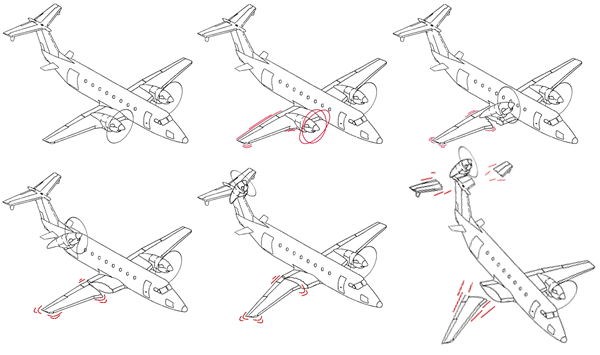
Signal analysis of data acquired from the CVR (cockpit voice recorder) revealed the presence of structural acoustic signals that indicated the failure onset and the resulting aircraft breakup. The present study illustrates that damage detection may be carried out by using an existing system that acts as a latent signal transducer.
The Lockheed Electra, an earlier commercial turboprop airliner, encountered the first documented case of propeller whirl flutter. Whirl flutter is a catastrophic event but does not generally occur unless an engine truss (or mount) has been significantly damaged [2]. This consideration prompted a reliability study of aircraft like the one involved in the ALPA investigation to estimate the characteristic life of the engine truss and to determine if a history of truss problems existed [3]. Evaluation of FAA (Federal Aviation Administration) SDR (Service Difficulty Report) data revealed that six engine truss designs had been implemented in response to truss cracking over the ten year history of the aircraft. One commuter airline documented over seventy cases of cracked trusses, some detailing complete separation of truss tubes. This airline had sixteen of these aircraft, all three years old or less. Even though airline companies were encouraged to inspect the critical areas as frequently as every 100 hours, in two cases up to eight cracks were discovered in a single truss between inspections. The FAA Principal Aviation Safety Inspector for Airworthiness expressed his concerns about this matter in a November 1989 memorandum.
The reliability study indicated a decrease in truss characteristic life as the truss designs evolved; the failure mode was transitioning from a normal wearout to a critical early wearout mode. The latest truss design demonstrates a wearout mode closely approaching an infant mortality condition. The truss reliability study, for example, estimated a characteristic life of 4282 hours for the most current operational design; this falls far short of the characteristic life design goal of 30,000 hours [3]. Two additional failure modes were found in the four vibration isolation mounts that tie the engine to the tubular truss; these failures were noted to be occurring due to delamination and dislodgment of the isolator mount. Both the truss cracking and isolator failure modes are critical with respect to whirl flutter. Examples of truss cracking and vibration isolator failures are shown in Figure 2. While 253 FAA SDR's were identified on the cracking problem, over 500 reports have been found for the vibration isolation mount failures. Studies are underway to determine if delamination, dislodgment, and truss cracking are statistically correlated. The reliability picture may be more critical than that indicated by cracking alone.


Click on a picture above to view the larger version.
To further evaluate the possibility of whirl flutter, two independent analyses were performed. The studies indicated that whirl flutter is not a problem for the undamaged truss but with a failure of two or more truss tubes, the flutter speed of the aircraft is within its flight envelope of 96 to 250 knots. Based on radar data, the aircraft speed at the time of breakup was approximately 185 to 195 knots. The analyses for selected types of trusses and damage indicated whirl flutter frequencies in the range of 0.7 to 1.0 Hz. A stable whirl and a whirl flutter motion, occuring below and above the critical speed respectively, are both depicted in Figure 3.
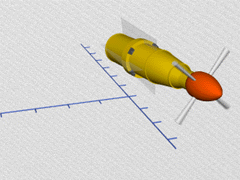
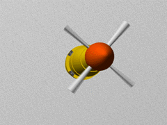
Click on a picture above to view a quicktime movie (Both 8.8 Meg).
The results of the reliability and whirl flutter analyses indicated that the CVR should be checked for critical acoustic signatures. At the time of the accident, the CVR was the only on-board flight recorder available for analysis [4]. Four-track, 30-minute, continuous-loop CVR's are required on civilian airliners to provide an analog recording of cockpit voice and radio communications. No significant voice stress characteristics were noted throughout the tape, leading to the conclusion that the accident occurred without warning to the pilots. The tape was evaluated for signals characteristic of whirl flutter and the first propeller blade passage frequency. The blade passage frequency would be dominant due to the mass unbalance resulting from the damage to the engine truss during whirl flutter. The frequencies recorded on the tape were correlated with an engine flight idle condition of 1550 rpm at the time of the breakup.
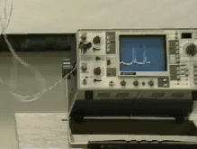
When the CVR was replayed at constant speed, the recorded vibration components were transformed into time- and frequency-domain modulations of carrier tones that were being delivered to the tape heads. There were at least four such carrier tones present on different tracks of the CVR. For example, a landing-gear warning-horn signal consisting of 500 Hz tone bursts of 330 ms (millisecond) duration and spaced 700 ms apart in period was noted. The tone contained only 8 cycles of low-percentage-deviation frequency modulation at a 24 Hz rate, yet they were discernible with the unaided ear. These amplitude and frequency modulations were later confirmed by a signal analyzer (Fig. 4).
 Original tape speed(wav)
 1/4th tape speed(wav)


Click on a picture above to view the larger version.
Characteristic turbine engine sounds were recorded onto the CVR silent track through a process known as electroacoustics (Fig. 5) [5].


Click on a picture above to view the larger version.
This figure, derived from a Hewlett-Packard 3566A/67A Signal Analyzer, shows the landing, two engine braking, and single-engine 180-degree turn-around. Left and right engine out sequences are also included. The turbine frequencies ranged from idle (3000 Hz) to near full power (6000 Hz). The presence of signals recorded on the silent track is likely a result of the triboelectric effect acting on a vibrating signal line without a microphone but still connected to the CVR input amplifiers. Triboelectric currents are generated by charges created between a vibrating conductor and its insulator due to friction [6].
Triboelectric (18.8meg quicktime)
Close inspection of the amplified (30 decibel) time series from the silent track also revealed a periodic set of transient components occurring at a frequency of 0.86 Hz (Fig. 7).
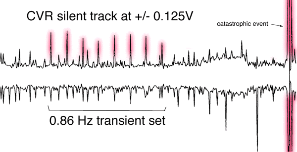
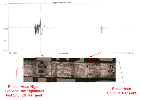
This frequency correlated with the structural dynamic and flutter analyses of the damaged truss and was found intermittently throughout the tape. These transient components are thought to be typical of acoustic impact signatures traveling through the structure which occur when a broken tube end impacts the joint where the fracture occurred. These transients became more frequent about 15 seconds before the in-flight breakup and then diminished to nearly zero at the end of the flight when the CVR shut off due to inertial over loads. Figure 8 shows the intense acoustic signals found at the end of the tape.
Magnetic Imaging of Tape
1. Airline Pilots Association Report, Beechcraft 1900C N811BE, 1992.
2. Serling, Robert J., The Electra Story, Garden City, N.Y., 1963.
3. Buschow, Monte, "A Study of the Reliability of In-Service Engine Mounts," M.S.E. Thesis, The University of Texas at Austin, Spring 1997.
4. Sendzimir, V., "Black Box," Invention and Technology, Fall 1996, pp. 26-32.
5. Frederick V. Hunt, Electroacoustics ( ASA Trade Paper, ISBN: 0-88318-401-X, 1982).
6. Keithley Company, Low Level Measurements, 4th Edition, no date.
*Appreciation is expressed to Arthur Wolk of Wolk and Genter for bringing this problem to our attention and providing additional insight on the accident. Our thanks also to John Murphy, for providing us with data and a professional pilot's interpretation of the event.Asppreciation is expressed to David McAllister, Kevin Kane, Terry Hill, Ann Mayoral, Cliff Hicks, John Carson, and Ernesto Alvarez for their review of the study.