Rene Boonen,
rene.boonen@mech.kuleuven.ac.be and Paul Sas
KU Leuven Faculty of Applied Sciences
Department of Mechanical Engineering, P.M.A.
Celestijnenlaan 300B
B-3001 Heverlee
Belgium
Telephone: (+32) 16 322480
Telefax: (+32) 16 322987
Popular version of paper 2pSAb
Presented Tuesday afternoon, March 16, 1999
ASA/EAA/DAGA '99 Meeting, Berlin, Germany
The reduction of external noise from cars and trucks is nowadays an important issue. The legislators are continuously lowering the noise emission standards in the different countries. Also, the combustion engine developers increases the engine efficiency by lowering inlet and outlet valve resistance. As consequence, exhaust system manufacturers have to develop exhaust systems which combines a higher noise attenuation level with a lower flow resistance.
The engine noise is caused by pressure pulses released by the exhaust. When the
expansion stroke of the engine comes to his end, the outlet valve opens
and the remaining pressure in the cylinder discharges as a pulse into the
exhaust system. These pulses are between 0.1 and 0.4 atmosphere in amplitude,
with a pulse duration between 2 and 5 milliseconds.
The frequency spectrum is directly correlated with the pulse duration.
The cut-off frequency lies between 200 and 500 Hz.

A passive exhaust system attenuates the noise by absorption and reflection. The acoustic waves are reflected back and forth into the exhaust system. At each reflection, the sound waves lose energy. As result, only a fraction of the noise leaves the exhaust outlet.
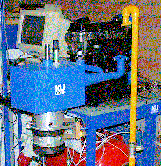
The proposed active exhaust system attenuates the noise in a very different way. The photograph presents the active exhaust system, which is the blue part mounted on the engine block. It consists of a buffer volume which is connected to the exhaust outlet of the engine and on which an electrically controllable valve is mounted. The engine acts as a volume velocity source and pushes the flow into the buffer volume. The valve is controlled such that only the mean flow passes the valve. The flow fluctuations are stored temporally in the buffer volume. As result, the flow out of the exhaust outlet is free of fluctuations, and consequently free of noise.
To develop the active exhaust system in an easy way, a cold engine simulator is developed. On the photograph, the cold engine simulator is the part on wich the active silencer is mounted. This machine generates realistic engine exhaust noise with the gas flow using compressed air. It permits to study acoustical and flow-dynamic phenomena in exhaust systems and to experiment with new concepts of exhaust systems without taking precautions against the hot corrosive gases of a real engine.
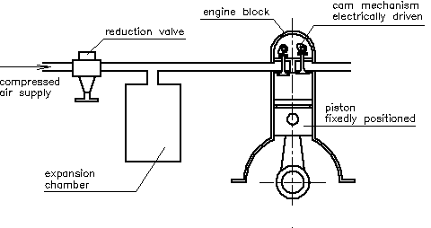
In a combustion engine, the pressure enclosed in the cylinder discharges in the exhaust as soon the outlet valve opens. The piston is at his lower dead point and the cylinder volume changes only 10 a 15% during the escape time of the pulse. This means that the exhaust pulse can be approximated by the discharge of a constant volume. This assumption forms the basis of the cold engine simulator. A scheme of it is presented in the figure below.

It consists of a regular engine block whose pistons are fixed at their lower dead points. The inlet collector is connected via an expansion vessel and a pressure reduction valve to a normal pressurized air supply network. The cam mechanism of the engine block is driven by an electric motor. The supplied pressure at the inlet collector is equal to the pressure in the cylinder of an operational combustion engine at the end of the expansion stage. During the inlet stage, the cylinder charges at the same pressure level as applied at the inlet. When the outlet opens, the cylinder discharges and the pressure pulse enters the exhaust. The discharge takes a few milliseconds. These pressure pulses are compared with the pulses from a real combustion engine. The shape and frequency spectrum of the pulses are very similar.

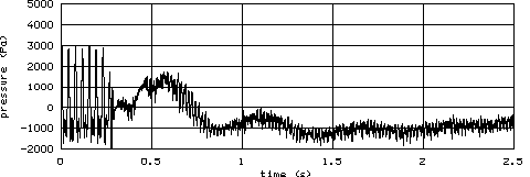
The active silencer is tested on this setup using two types of electronic controllers. The first one tested is a feedforward non-adaptive controller resulting in a sound attenuation of 13 dBA. The second one is a feedback controller, resulting in 16 dBA attenuation. The figure at the left presents a measurement of the sound pulses out of the exhaust outlet. The controller is started after 0.35 seconds. The backpressure to the engine is between 0.03 and 0.1 atmosphere, while a passive system with the same attenuation needs 0.15 to 0.3 atmosphere.
The feedforward controller uses two sensors, one for pressure in the buffer volume and one for the flow through the control valve. The feedback controller uses only one sensor for the pressure after the control valve. Despite the better performance and the simpler instrumentation, the feedback controller is too sensitive for the dynamics of the engine and the exhaust system. At this instant, feedforward controllers are again in investigation, in order to eliminate the flow sensor.
The last step in the development is to rebuild the active silencer for a car. In our current planning, the active silencer for a car should be ready in June 1999.
The development of the cold engine simulator and the active silencer is part of the Flemish projects VLIM/0/9328 and IWT-960197 on the research of the application of active noise control for internal combustion engines. The partners in this project are BOSAL International N.V. (see www.bosal.be ) and the K.U.Leuven, division P.M.A. (see www.kuleuven.ac.be , www.mech.kuleuven.ac.be/pma/pma.html )