Waymond Scott, Jr.,
Christoph Schroeder, Kangwook Kim, Cheng Jia
Georgia Institute of Technology, School of Electrical and Computer
Engineering
Atlanta, Georgia, 30332
Peter Rogers, James Martin, Gregg Larson
Georgia Institute of Technology, Woodruff School of Mechanical Engineering
Atlanta, Georgia 30332
Popular version of papers 4pPA2, 4pPA3, 4pPA4, and 4pPA5
Presented Friday afternoon, June 2, 2000
139th ASA Meeting, Atlanta, Georgia
It has been estimated that there are 100 million land mines buried throughout the world, responsible for approximately 26,000 injuries and deaths per year [1]. Over the last 50 years, extensive effort has been expended developing techniques for locating land mines. These techniques are reasonably successful under favorable conditions; however, all of these techniques fail under unfavorable conditions. For a mine detection technique to be successful there must be sufficient contrast between the properties of the mine and the earth so that the mine can be detected. There must also be sufficient contrast between the properties of the mine and common types of buried clutter such as rocks, roots, cans, and metal objects. For example, metal detectors are used to locate land mines in all types of soils and terrains. However, they also locate every shell casing, can, and scrap of metal in the detection area, resulting in an unacceptable false alarm rate. This is particularly a problem when searching for low-metal land mines.
New approaches to land mine detection are being studied to improve the detection rates and to reduce the false alarm rate of the existing detection techniques. One approach, being pursued at Georgia Tech, involves the simultaneous use of elastic and electromagnetic waves to detect both anti-tank (AT) and anti-personnel (AP) mines [2,3]. The fundamental approach is to excite elastic waves in the soil and then measure the surface displacements throughout the detection area to determine the land mine locations. The current configuration of the system, shown in Figure 1, uses an electrodynamic shaker in direct contact with the soil to excite elastic waves. As the waves propagate through the scan region, the surface displacements are measured using a radar. Current research efforts include both experimental and numerical models of the system. In Figure 2, the elastic waves generated by the shaker are shown propagating in the soil as determined by the numerical model. The surface waves as well as the sub-surface waves can be seen in the numerical results. Two- and three-dimensional models have been used to study the propagation of elastic waves and the effects of buried land mines [4,5].
Elastic techniques show considerable promise for the reliable detection of all types of buried mines, even low-metal anti-personnel mines. The reason for this is that mines have mechanical properties that are significantly different from soils and typical forms of clutter. The shear wave velocity, for example, is more than 20 times higher in the explosive and plastics used in typical mines than it is in the surrounding soil. In addition, mines are complex mechanical structures with a flexible case, a trigger assembly, air pockets etc. The complex structure gives rise to structural resonances, non-linear interactions, and other phenomenology that is atypical for both naturally occurring and man made forms of clutter. This phenomenology can be used to distinguish a mine from clutter. In Figure 3, the interaction of the elastic waves with a buried AP mine can be seen based upon the numerical model. The waves are seen to propagate past the mine location, scattering and exciting the mechanical resonance of the mine, in the movies shown in Figure 4 and Figure 5. Figure 4 shows the sub-surface displacements while Figure 5 shows the surface displacements from the numerical model. Similar effects are seen in the experimental results shown in the movie in Figure 6.
The images formed from data taken in experimental measurements indicate that both AT and AP mines can be detected even in the presence of surface vegetation and buried clutter. A small AP mine and typical forms of clutter (rocks and sticks) were buried in the scan region with 2.3 cm of pine straw covering the surface. The burial locations, pine straw covered scan region, and relative sizes of the buried objects are indicated in Figure 7. The image shown in Figure 8 was generated from the measured surface displacements to identify the location of the buried land mine. Similarly, AT mines can be seen in the unprocessed measurement data. In the movie in Figure 9, an AT mine was buried 4cm deep. The elastic waves are seen as they propagate through the scan region, scattering off of the mine and exciting the mine's resonance. In another test of the experimental model, four AP mines, one AT mine, and four rocks were buried in the scan region. The burial locations and relative sizes of the mines and rocks can be seen in Figure 10. The image formed from measurements of the surface displacements identified the locations of the land mines in Figure 11.
The current research emphases are to evaluate alternate sources and sensors [6,7,8], characterize elastic wave propagation in typical soils, improve both numerical and experimental models, and develop and test a system capable of field measurements.
Contact Information
For further information, please contact W. R. Scott, Jr., at either
waymond.scott@ee.gatech.edu
or (404)894-3048.
References
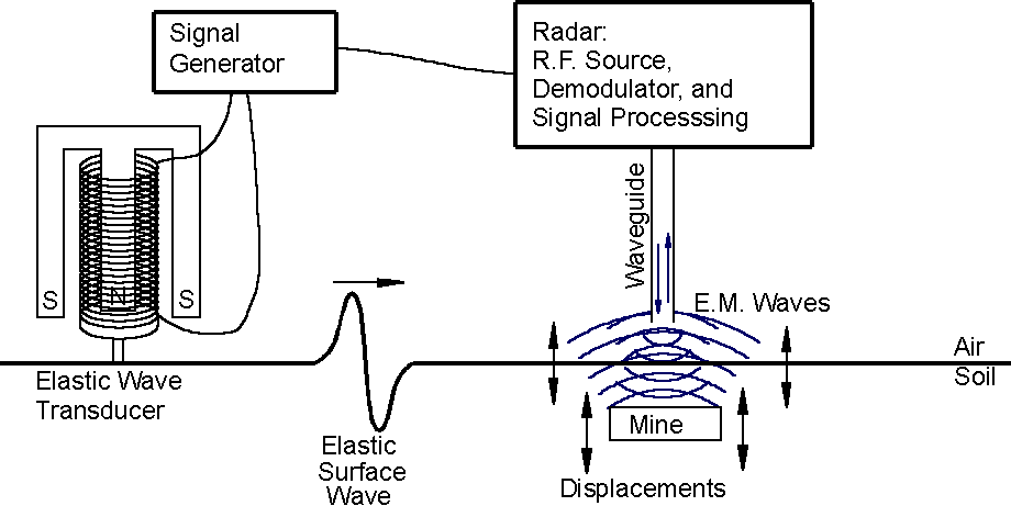
Figure 1: Current System Configuration. The elastic wave transducer generates elastic surface waves which propagate through the scan region while a radar-based sensor measures the surface displacements of the soil throughout the scan region. A characteristic mine signature is observed immediately above the buried mine in both numerical and experimental models. Back to text.
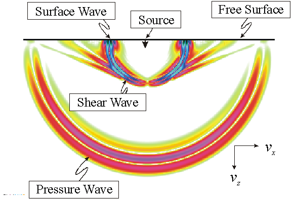
Figure 2: Identification of Elastic Waves. Pressure, shear, and surface (Rayleigh) waves are generated by the elastic wave source. The numerical model measures displacements along the free surface and as a function of depth as shown here while the experimental model measures displacements only along the free surface. Back to text.
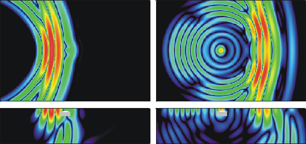
Figure 3: Results from Numerical Model. These images show the surface and sub-surface displacements at two separate instants in time. In the two left images, the elastic waves have not propagated to the location of the buried mine. In the two images on the right, the elastic waves have propagated past the mine location. The upper images show the surface displacements while the lower images show the sub-surface displacements. Back to text.
Figure 4: Pseudo-color movie of sub-surface displacements as a function of time from the numerical model. An anti-personnel mine was buried 2cm deep in the soil. The elastic waves are seen propagating through the soil, scattering off of the buried mine, and exciting the mines resonance. Push the arrow to start the movie. Back to text.
Figure 5: Pseudo-color movie of surface displacements as a function of time from the numerical model. An anti-personnel mine was buried 2cm deep in the soil. The elastic waves are seen propagating through the scan region, scattering off of the buried mine, and exciting the mines resonance. The circle indicates the mine location. Push the arrow to start the movie. Back to text.
Figure 6: Pseudo-color movie of surface displacements as a function of time from the experimental model for an anti-personnel mine buried 2cm deep. Push the arrow to start the movie. Back to text.
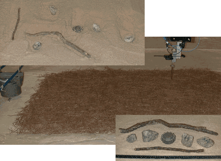
Figure 7: Configuration for a test including a single anti-personnel mine, buried clutter, and surface vegetation. The burial locations, the scan region covered by pine straw, and the relative sizes of the buried objects are shown in the photographs. The elastic wave transducer is shown to the left of the scan region while the radar is shown at the right end of the scan region. Back to text.
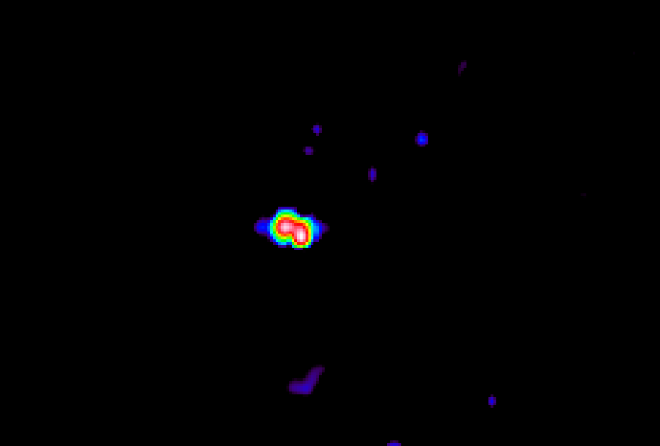
Figure 8: Image of anti-personnel mine with surface vegetation and buried clutter. This image was formed from the experimental data taken from the scan region shown in Figure 7. Back to text.
Figure 9: Pseudo-color movie of surface displacements of the sand as a function of time. An anti-tank mine was buried 4cm deep in the scan region. This movie was made from unprocessed experimental measurement data. The elastic waves are seen propagating through the scan region, scattering off of the buried mine and exciting the mines resonance. Back to text.
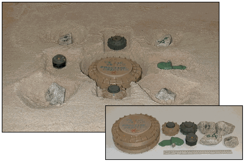
Figure 10: Configuration for test to locate both anti-personnel and anti-tank mines in the presence of buried clutter. The photographs show the locations and relative sizes of the one anti-tank mine, four anti-personnel mines, and rocks. Back to text.
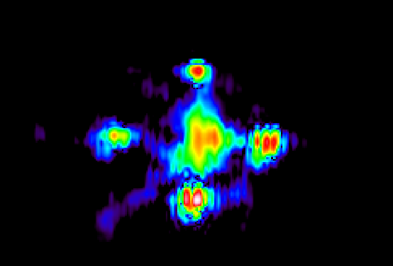
Figure 11: Image formed from experimental measurement of the scan region shown in Figure 10. Back to text.