

How Tires Make Noise
Dan Borza, borza@insa-rouen.fr, and Ioana Nistea, ioana.nistea@insa-rouen.fr
Institut National des Sciences Appliquées,
Laboratoire de Mécanique de Rouen, France
Popular version of paper 2aSAb1
"Wavelet-based data processing for comparative study of noncontact measurement techniques for vibroacoustics"
Introduction
Noise reduction is one of the major concerns in refining vehicle design. In recent years, due to considerable efforts in engine noise reduction, tires and their interaction with the road have become one of the major sources of car noise.
Determining the vibration parameters of tires may provide useful information on the contributions of different parts of the tire to the resultant noise, making it possible to improve their design.
This work aims at determining, by Electronic Speckle Pattern Interferometry (ESPI), the most important mode shapes and resonant frequencies of a tire. This non-contact laser measurement technique is an efficient tool for vibration analysis, providing full field and real time information on surface displacement.
The measurement technique
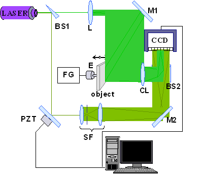
The ESPI setup for out-of-plane measurements, presented in fig. 1, is composed of a continuous wave laser source, a few optical components (beamsplitters, mirrors and lenses), a CCD camera and a computer provided with a frame grabber and adequate imaging software.
The laser wave emitted by the source is divided by the beamsplitter into two waves, the first one creating the object beam and the second one creating the reference beam.

Fig.1: Phase stepped ESPI setup
The first wave travels through the expanding lens L and is directed by mirror M1 onto the object surface, from which it is reflected and focused by the camera lens CL on the CCD sensor.
The second wave is reflected by the beam splitter BS1 and the PZT mirror, then expanded by a spatial filter SF and redirected, through mirror M2, to the beam splitter BS2, onto the CCD sensor, where it interferes with the object beam.
The path difference between the two beams creates an optical phase difference between them. This phase difference modulates the interference pattern recorded by the digital camera. For static measurements, the difference between two interferograms, one recorded in an initial, reference state of the object and the other one in a second, strained state produces a fringe pattern. This fringe pattern contains the necessary information on the relative displacement field.
The technique also allows measuring vibrations. In this case, the object is forced to vibrate harmonically by a shaker (E) driven by a variable frequency generator (FG). As the camera’s acquisition time is much higher than the object’s vibration period, the information contained by the recorded images is integrated over several periods of vibration.
The operator examines on a display monitor the object image covered by a pattern of interference fringes. These fringes represent a contour map of the out-of-plane vibration amplitudes.
Experimental setup
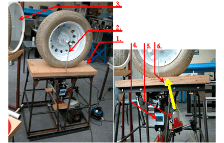
The experimental setup for the vibration measurement of the tyre is shown in fig. 2. A static load of 4 kN is applied through the test table (1) with two rods (2) and monitored by two dynamometers (4). In order to increase visibility, the surface of the tire is covered with white paint. A supplementary mirror (3) allows observation of the thread region.

Fig 2: Test setup
The vibration is applied on the thread near the limit of the tire foot print (6). Under real, rolling conditions, this part of the tire corresponds to the excitation point.
Experimental results
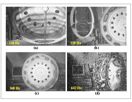
Most of the tire’s resonant modes are situated in the 40 – 1100 Hz frequency range. At low frequencies (under 170 Hz) most of the modes engage into vibration the rim and parts of the test table and loading mechanism (fig. 3.a). We found an important number of resonant modes in the 170 - 650 Hz frequency range. Due to their high density, these modes are poorly separated in frequency, which yields coupled mode shapes, highly variable with excitation frequency shift (fig. 3.d). The vibration amplitudes are generally decreasing from the excitation point to the opposite end of the tyre’s diameter (fig. 3.c). We can also observe that in most of the cases, the vibration amplitudes on the thread of the tire are more important than those situated on the sidewalls (fig. 3.b).

Fig 3: Vibration modes of the tire