


“Smart Foams” for Enhancing Acoustic Absorption
Pierre Leroy, pierre.leroy@usherbrooke.ca
Groupe d’Acoustique de l’Université de Sherbrooke (GAUS)
Faculté de Génie
Département de génie mécanique
Université de Sherbrooke
2500 Blvd. Université
Sherbrooke (Québec) Canada
J1K 2R1
Alain Berry, alain.berry@usherbrooke.ca ;
Noureddine Atalla, noureddine.atalla@usherbrooke.ca ;
Philippe Herzog, herzog@lma.cnrs-mrs.fr
Popular version of papers 2117 (3aSAb3) and 2503 (5aSAb10)
Presented Wednesday 2 July 2008 , 11:20 ROOM 252B
and Friday 4 July 2008, 12:20 ROOM 253
Acoustics’08 Paris, France
Goal
Improve acoustic absorption in the low frequency range.
Context
Noise reduction can be practically achieved using passive sound absorbing materials such as foams or fibrous materials. Improving low frequency absorption is an important problem in acoustics. The acoustic absorption of a material can be defined as the ratio between the acoustic energy incident on the material surface and the acoustic energy that is absorbed by this surface.
Passive materials generally provide adequate absorption at medium and high frequencies but are inefficient in the low frequency range, where acoustic wavelengths are large. Melamine foam, which is one of the most effective absorbing materials, has an absorption coefficient close to 1 at frequencies higher than 1000 Hz for a material thickness of 5 cm. At frequencies lower than 1000 Hz, no passive material really provides a large absorption for a small thickness. On the other hand, active control, which aims at minimizing a physical quantity (sound pressure, structural vibration) by generating an appropriate out-of-phase control signal, is effective in the low frequency range but ineffective at higher frequencies due to real-time computational limitations.
What is a “smart foam”?
A smart foam is a sound absorbing foam with one or more embedded actuators, making it possible to combine the passive properties of the foam material with sound cancellation mechanisms of active control (figures 1 and 2). Our study is dedicated to the maximization of acoustic absorption, but smart foams can also be used to minimize the acoustic transmission through a surface or the radiation of vibrating structures (1, 2, 3, 4, 5). In the acoustic absorption control case, the embedded actuators are used to minimize the wave reflected by the foam at low frequencies, whereas the foam passively absorbs the incident wave at medium and high frequencies. The actuator that we used in this study is a PVDF (Polyvinylidene fluoride) film which is a very thin polymeric piezoelectric material. The foam used is a melamine foam which has the advantage of being very lightweight. An electrical field applied across the film thickness generates in-plane displacements, which couple to radial displacements because of the film curved shape (figure 2). These radial displacements in turn generate counter vibration and sound that oppose the incident sound wave. In addition, sensors must provide the residual acoustic or structural information to continuously update the control actuator inputs. The combination of passive performances of the foam and active ability of the actuators provides a broad band absorber which has low space and weight.
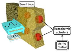
Figure 1 : Principle of smart foam for absorption.
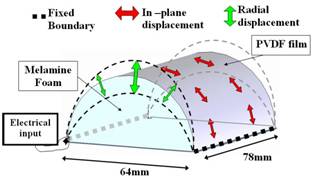
Figure 2: Schematics of the smart foam prototype and actuation mechanism.
Some of the issues related to the design and use of smart foams:
The inclusion of actuators into the foam and the implementation of active control raise certain questions that still need to be investigated:
Only advanced numerical modeling can help optimizing smart foams
Some analytical models have been developed for poroelastic and piezoelectric materials but these models are valid for simple geometries. Only a finite element (FE) model can accurately predict the effects of complex geometry, dissipation mechanisms, actuator positions, maximum incident pressure amplitude that can be controlled and properties of absorbing material used.
Only few models have been developed to describe the complex acoustical and structural behaviour of smart foams. Mathur et Al (4) proposed a 2D FE model able to couple poroelastic, acoustic, elastic and piezoelectric media. They used a (u,U) formulation for the poroelastic media with linear elements. The piezoelectric medium was modeled with a linear plate element with only one direction of strain. Akl et al (5) have developed a 2D FE model for poroelastic media coupled with elastic and piezoelectric domains. They developed a new type of smart foam substituting the PVDF by piezoelectric fibers modeled in 1D. All the above models use a (u,U) formulation for the porous media and only linear elements in the FE implementation. Moreover, the piezoelectric modeling is limited to one direction of strain, which is erroneous for a PVDF film. In addition, no experimental validation has been directly conducted on the smart foam model in a radiation configuration.
In our study, a full 3D finite element modeling tool for smart foam has been developed. The tool predicts acoustical and structural behaviour of coupled media such as piezoelectric, elastic, poroelastic and fluid. The modeling of the poroelastic media uses the (u,p) formulation proposed by Atalla et al (6) which is less time-space consuming than the (u,U) formulation, and the coupling conditions proposed by Debergues et al (7) . The poroelastic model has been extended to orthotropic foams. The modeling of the piezoelectric media has been developed in 3D using the equations proposed by Tiersten (8). A reduction to 2D using shell assumption has also been developed in order to be able to model both volume and surface piezoelectric media. The numerical implementation uses quadratic elements with 20 nodes for volume elements and 8 nodes for surface elements. The various types of loads that have been validated are imposed displacements, point forces, applied pressure and applied electric potential for piezoelectric domains.
The formulation used makes it possible to calculate in local and global scale the classical physical indicators, such as squared sound pressure and structural velocity, dissipated power, power balance of the system, absorption coefficient, surface impedance and optimal actuator input under active control. This allows parametric studies to be conducted and optimal smart foam designs to be made. A schematic diagram of the model is shown in the figure 3.
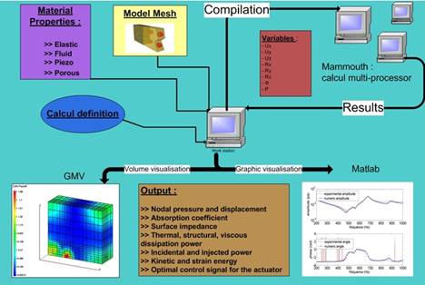
Figure 3: Schematics of the Finite Element Model of Smart Foams
Experimental validation of the model
The validation focuses on the acoustical and structural behaviour of the coupled smart foam structure with no active control implementation for the moment. The experimental validation has been done using a prototype realized with a PVDF film bonded to melamine foam having a half cylinder shape (9) (figure 2). The smart foam is backed by a small cavity (figure 5) equipped with electric connections in order to feed the PVDF and to ensure a correct embedding for the PVDF. Plexiglas flanges are placed on the foam of the back cavity that is not covered with PVDF to ensure tightness with the back cavity. The smart foam and the cavity form a so-called active cell. The cell is mounted at the end of an impedance tube that has a cut off frequency of 2200Hz (figure 4), the other end of the tube being rigidly closed. Passive absorption, radiated pressures and displacement of the foam and the PVDF are presented on the figure 6.
Figure 4: Measurement tube
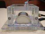
Figure 5: “smart foam” cell provided with electric jaws
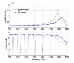
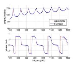
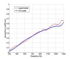
Figure 6: comparison of the FE and experimental data. (a): passive acoustic absorption; (b) : sound pressure at the closed end of the tube, (c): structural displacement at center of the foam surface.
The model shows an almost perfect agreement with the measurement of the radiated sound pressure in the waveguide and gives correct tendencies for the vibration response of the smart foam, especially in the low frequency range where the smart foam is used for active control.
A tool to understand the physics of smart foams
The code makes it possible to understand how a smart foam creates optimal acoustic absorption. Here, two theoretical configurations are presented. The first is a smart foam with a PVDF film virtually permeable to sound waves and the second is smart foam with an impervious PVDF. Figures 7 and 8 show the power dissipated by viscous processes in the foam at 25 Hz (a low frequency) for the two configurations. Figure 9 shows the amplitude and phase of the optimal control input to the PVDF actuator (the phase reference is the air particular displacement on the foam surface). The displacement of the PVDF is proportional to the applied voltage. It appears that the smart foam with an impervious PVDF operates in order to make the impedance of the smart foam equal to the characteristic impedance of the air. The displacement of the PVDF is in phase with the displacement of the air particles in front of the foam. The viscous dissipation in the porous is then very small. In contrary, the smart foam with a permeable actuator acts to maximize the viscous dissipation power. The displacement of the permeable PVDF is then out of phase with the displacement of the air particles in front of the foam.
![]()
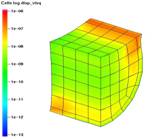
Figure 7: Viscous dissipation power (W) at 25Hz for a smart foam with a virtually permeable PVDF film achieving a perfect absorption

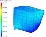
Figure 8: Viscous dissipation power (W) at 25Hz for a smart foam with a impervious PVDF film achieving a perfect absorption
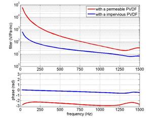
Figure 9: Optimal control input expressed as the ratio of the control voltage on the incident pressure amplitude (V/Pa-inc). Top: magnitude; Bottom: phase difference with the air particle displacement on the foam surface.
Smart foam experiments
The figure 10 shows the shape and the dimensions of the optimized prototype. Figure 12 gives the acoustic absorption coefficient measured in the waveguide of figure 4 for the control input shown on the figure 11.
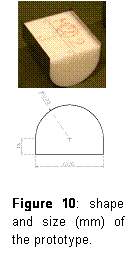
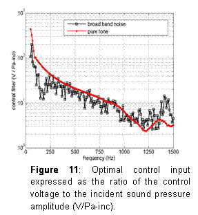
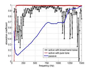
Figure 12: Passive and active absorption coefficient for pure tone or broadband disturbance
The active absorption of a pure tone primary sound wave is excellent. The smart foam allows complete absorption of an incident acoustic wave with a 103 dB SPL amplitude at 100 Hz. Although not as good as for a pure tone, the absorption of a broadband sound wave is significant. The smart foam has an authority sufficient to absorb a broadband acoustic wave with a 95 dB SPL amplitude above from 300 Hz. Absorption is limited at low frequency by the large distortion of the smart foam under 250 Hz.
Conclusion
A full 3D smart foam model was developed and experimentally validated. Clearly, the vibroacoustic prediction model is an effective tool to design and optimize hybrid active-passive absorbing materials. This model is general and can be used for any coupled structure involving fluid, elastic, poroelastic and piezoelectric media. A smart foam prototype including a semi-cylindrical melamine foam backed by a PVDF piezoelectric film was tested for active-passive absorption in a waveguide. The results show excellent agreement with the Finite Element model, and significant active absorption capability in low frequency. Based on our findings, the influential parameters of a smart foam are the passive absorption provided by the chosen foam, the control authority and linear response of the chosen actuator.
Main references:
1 C. Fuller, M. Bronzel, C. Gentry, and D. Whittington, “Control of sound radiation/reflection with adaptive foams", Proceedings - National Conference on Noise Control Engineering 429:436 (1994)
2 Guigou, C. and Fuller, C.R., “Control of aircraft interior broadband noise with foam-pvdf smart skin", Journal of Sound and Vibration vol220, 541:557 (1998)
3 C. Guigou and C. Fuller, “Adaptive feedforward and feedback methods for active/passive sound radiation control using smart foam", Journal of the Acoustical Society of America vol104, 226:234 (1998)
4 Mathur, G.P., Chin, C.L., and Simpson, M.A.and Lee,J.T., “ Structural acoustic prediction and interior noise control technology” (The boeing compagny, Long Beach, California) (2001)
5 Akl, W.N., Baz,A.M., and Whang,Y.and Zhu,J.and Zhang,M., “Smart foam for active vibration noise control", 164 :173 (NOISE-CON 2004, Baltimore, Maryland, USA) (2004)
6 N. Atalla, M. Hamdi, and R. Panneton, “Enhanced weak integral formulation for the
mixed (u,p) poroelastic equations", Journal of the Acoustical Society of America vol106, 3065:3068 (2001)
7 P. Debergue, R. Panneton, and N. Atalla, “Boundary conditions for the weak formulation of the mixed (u,p) poroelasticity problem", Journal of the Acoustical Society of America vol106, 2383:2390 (1999)
8 H. Tiersten, “ Hamiltons principle for linear piezoelectric media", 1523:1524 (IEEE)
(1967)
9 D. Bailo, K.C. ; Brei and K. Grosh, “Investigation of curved polymeric piezoelectric active diaphragms", Journal of Vibration and Acoustics, vol125, 145:154 (2003)
For further information, please contact : leroy@lma.cnrs-mrs.fr