William J. Elliot – welliot@cavtocci.com
Senior Consultant
Cavanaugh Tocci Associates
327F Boston Post Rd.
Sudbury, MA 01776
Popular version of paper 1aAA10
Presented Monday morning, October 31, 2011
162nd ASA Meeting, San Diego, California
Introduction
Communication at a distance has been a crucial part of our existence, whether used to secure a decisive military victory, streamline commerce, or link geographically distant regions that are part of the same nation or society. We often take for granted the interconnectedness available today with cellular phones and video conferencing, two forms of communication which include vocal interaction and all of the inflection, expression, and connotation that comes with it.
This direct auditory connection which has become integral to the electronic age does have an intriguing predecessor, however. Even before the widespread use of electricity in businesses and private homes, aural communication was possible at a considerable distance through the use of speaking tubes; conduits typically of metal or sometimes gutta percha (a form of latex obtained from a tree in Southeast Asia) that provided a direct link between various rooms within one building or between different locations on the same property/campus.
This paper examines the performance of a speaking tube system which was discovered during other unrelated acoustical work at an historic private residence in Cambridge, Massachusetts. Sound transmission via the speaking tube system was experienced in-person, and acoustical measurements were made to assess the performance of the speaking tube using current techniques and criteria. This investigation includes measurements to assess speech intelligibility and an examination of how the frequencies present in speech travel through the speaking tube from the kitchen pantry on the first floor to the main corridor on the second floor.
Historical Precedence
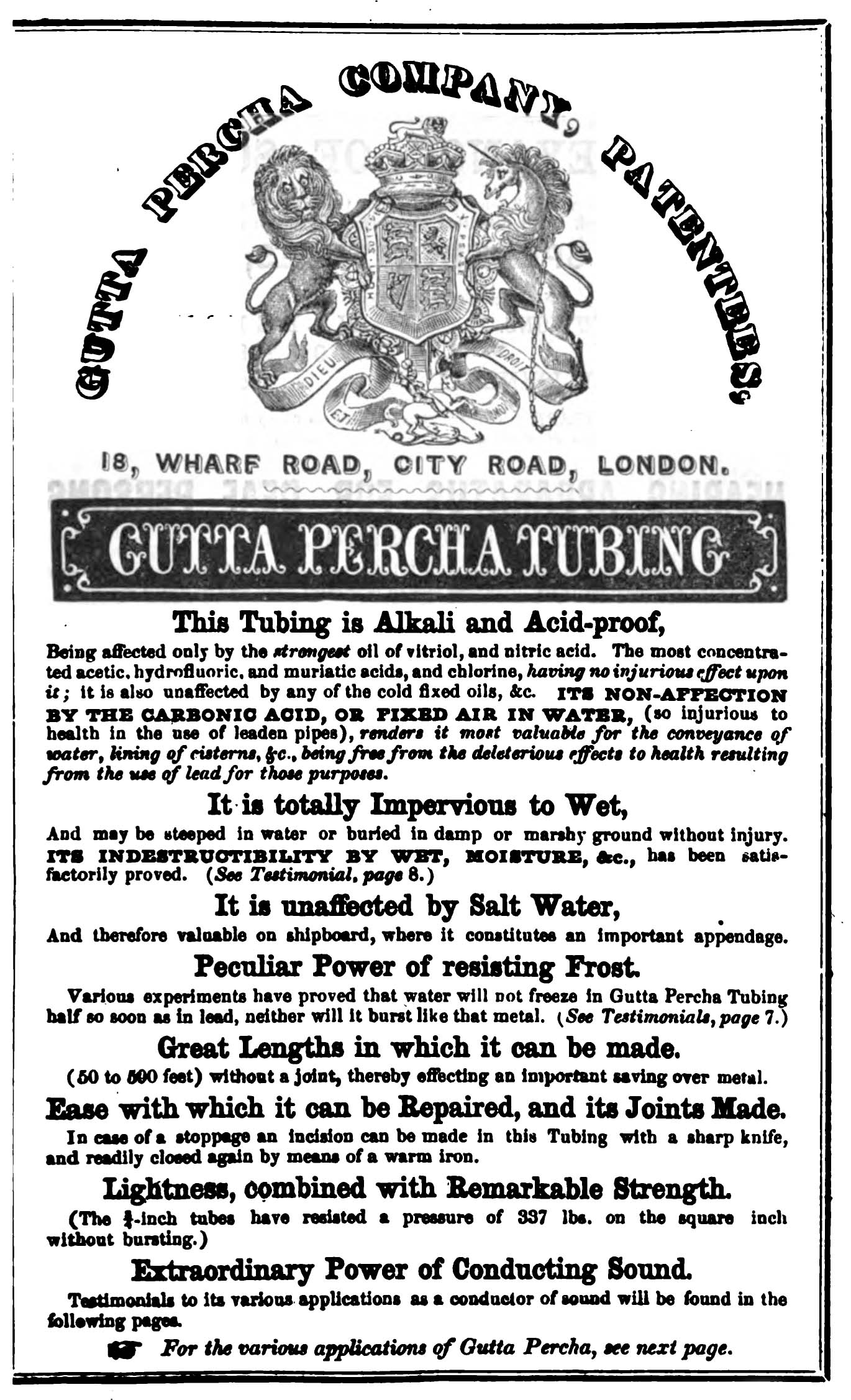
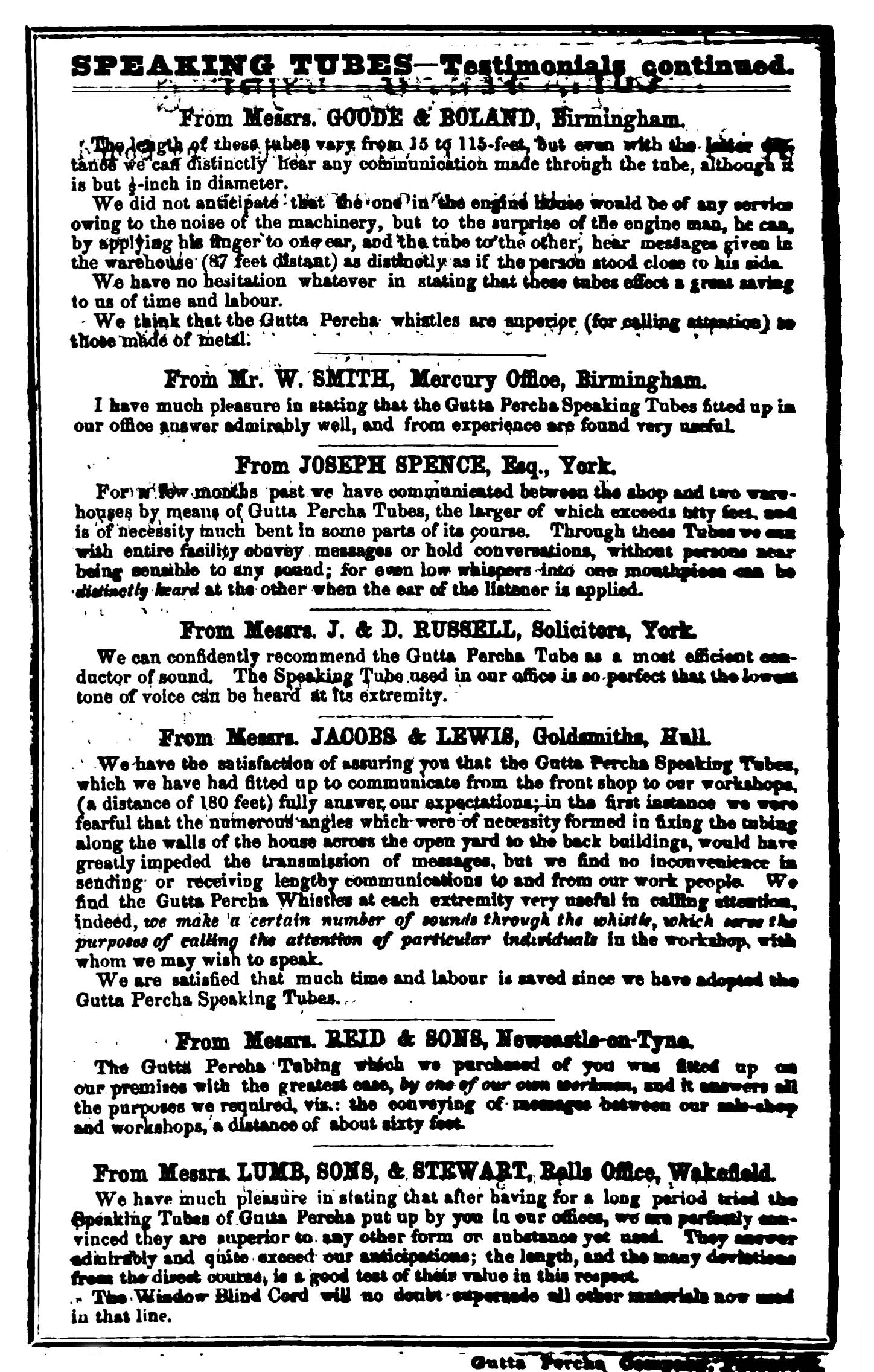
As early as 1849, references to speaking tubes may be found in American publications. An article in Scientific American from January 27 of that year expounds on the possibility that this “acoustic telegraph” could be deployed between U.S. cities such that “friends will be enabled to hear the voice of friends at 60 miles distant.” The article goes on to state that “it is not chimerical scheme by any means but one which sooner or later will be adopted on a small scale in every Factory, Foundry, and Public Building in the country.” It is also interesting to note that this article identifies gutta percha as the suitable material from which to build these acoustical telegraphs
(Figure 1 – Gutta Percha Tubing Advertisement)
(Figure 2 - Gutta Percha Speaking Tube Testimonials)
Decades before this Scientific American article, however, research by Jean-Baptiste Biot (1775-1862) confirmed the favorable characteristics for sound propagation that are offered by long, cylindrical conduits. Biot’s tests on water pipes in Paris up to 1,040 yards (951 m) in length confirmed that sound traveling through confined piping was a more efficient method of propagation than sound traveling in free space such that “a conversation could be kept up at the ends of a tube in a very low tone.” Biot also found that the transmitted sound level decreases as the diameter of the pipe increases, or its interior surface becomes rougher.2
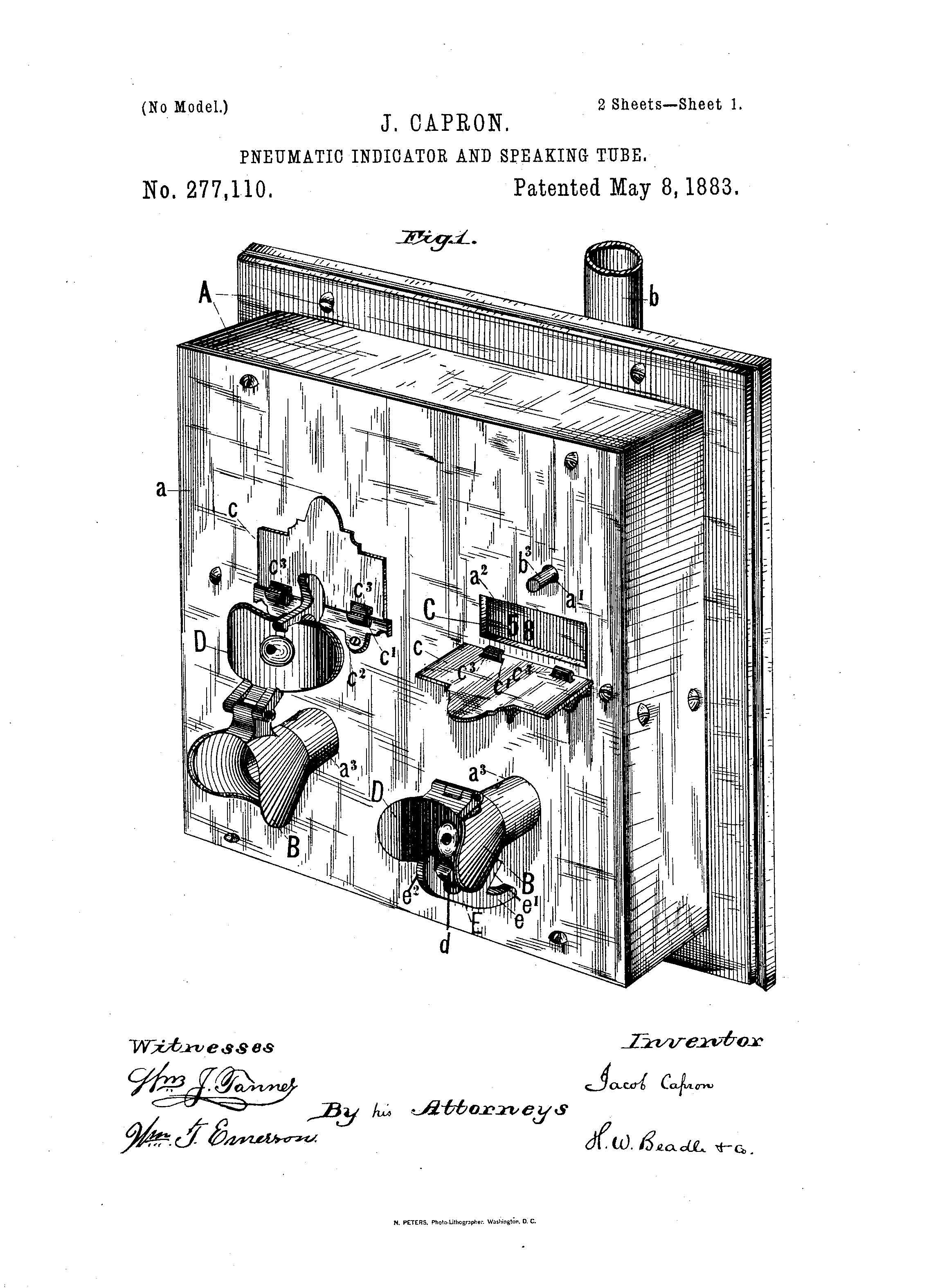
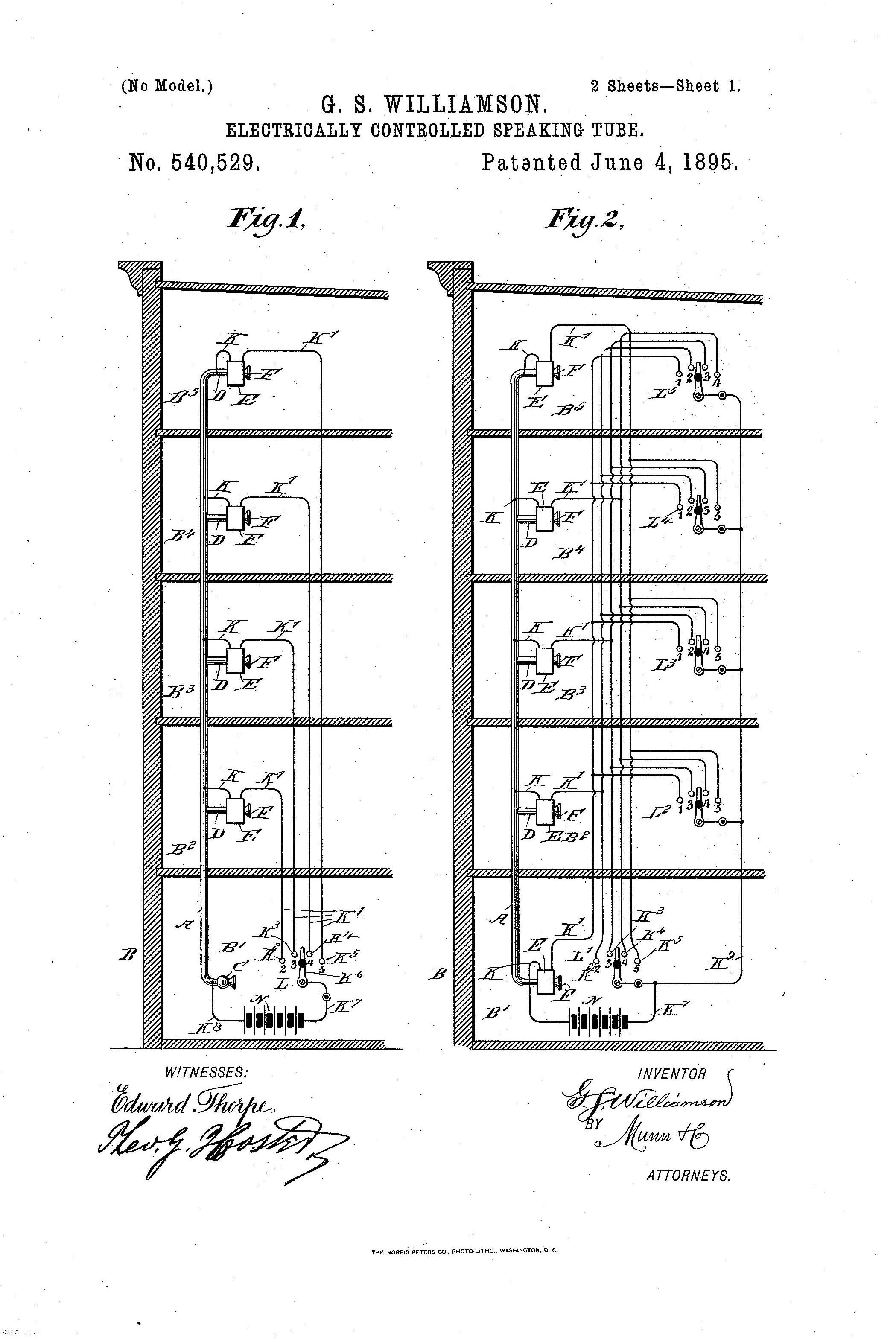
From the 1860’s through the 1890’s numerous patents may be found for components of speaking tube systems including innovative signaling whistles, pneumatic indicators, and even electrically-controlled speaking tube systems.3 These advances in speaking tube technology provided for more efficient communication between locations within a building such as a large corporate office or hotel, where several spaces may each be equipped with speaking tubes and knowledge of where the spoken message originated was important
(Figure 3 – Patent No. 277,110: Pneumatic Indicator for Speaking tubes)
(Figure 4 – Patent No. 540,529: Electrically Controlled Speaking tubes)
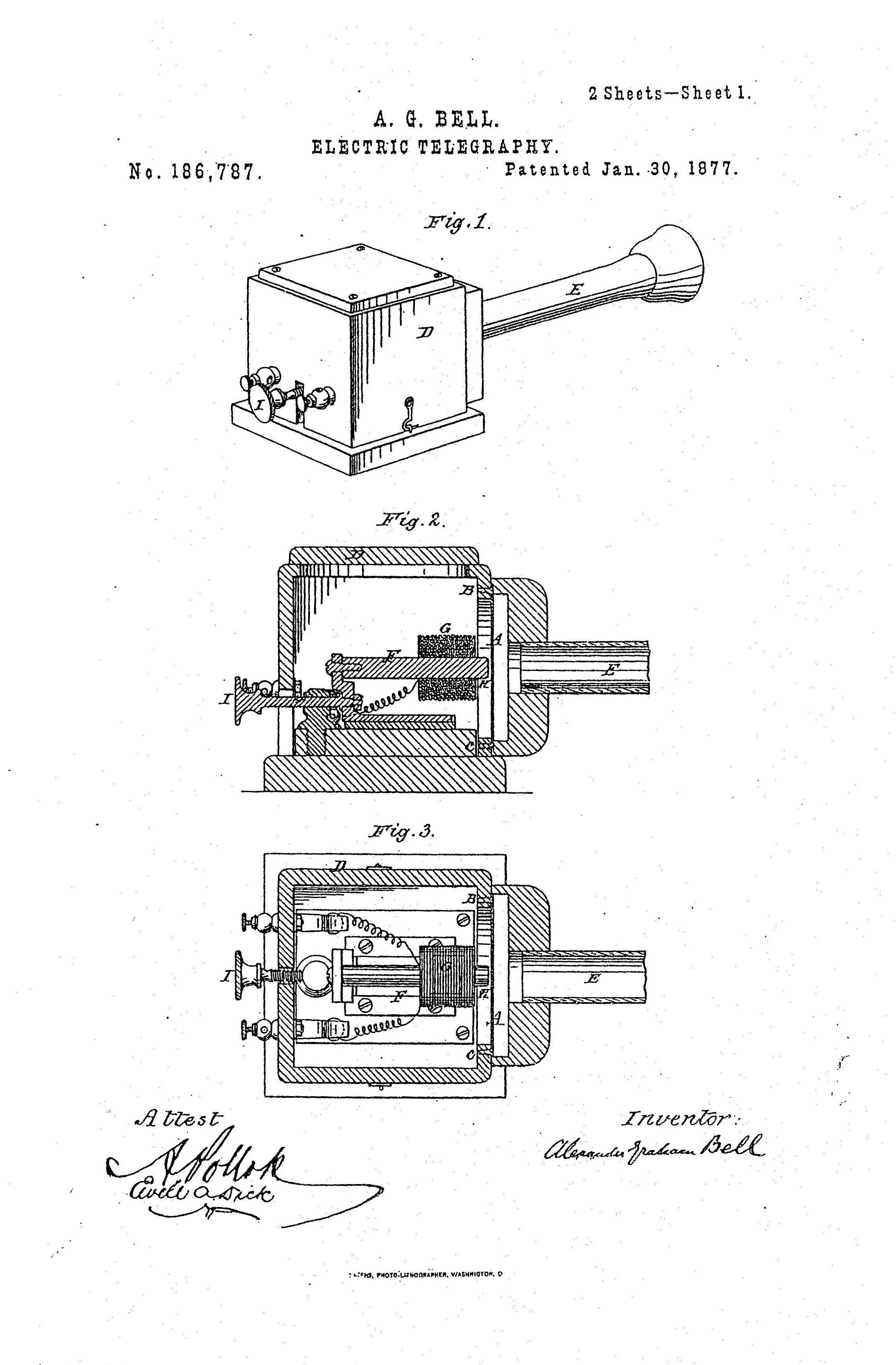
It is also interesting to note that in Alexander Graham Bell’s 1877 patent Improvement in Electric Telegraphy the early telephone includes a short speaking tube with a flared end, so “To convey an articulate message it is only necessary for an operator to speak in the neighborhood of his telephone, preferably through tube E, and for another operator at a distant station upon the same circuit to listen to the telephone at that station.”4
(Figure 5 - Patent No. 186,787: Improvement in Electric Telegraphy)
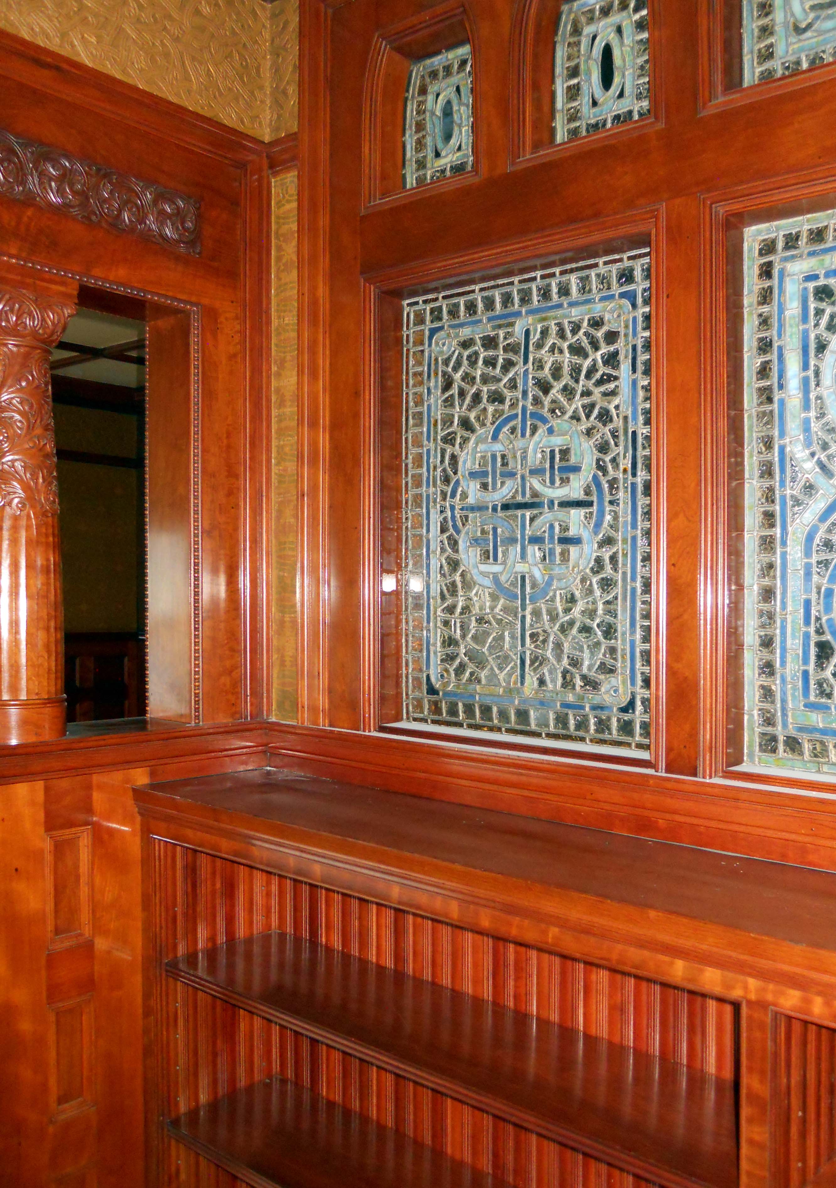
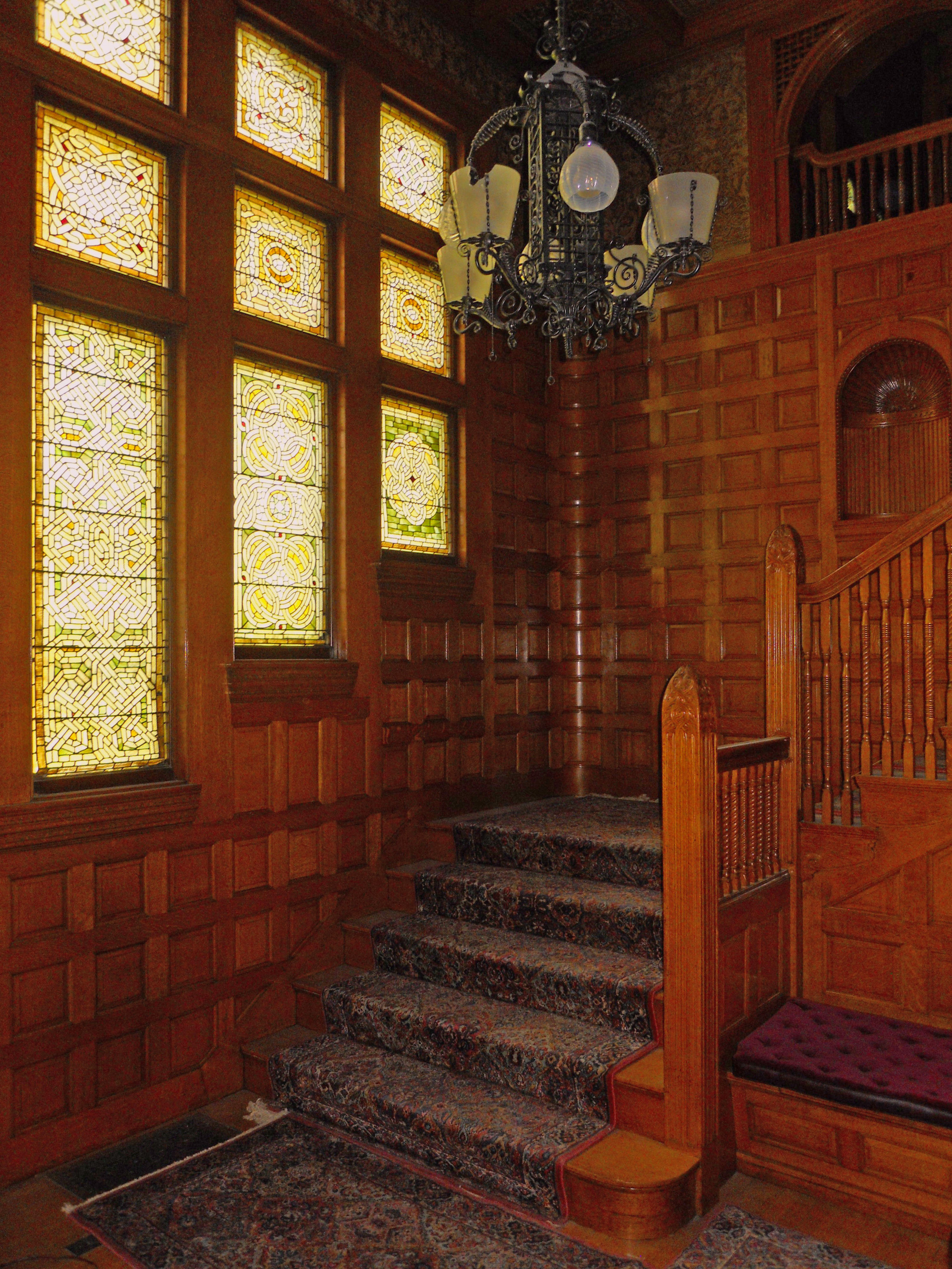
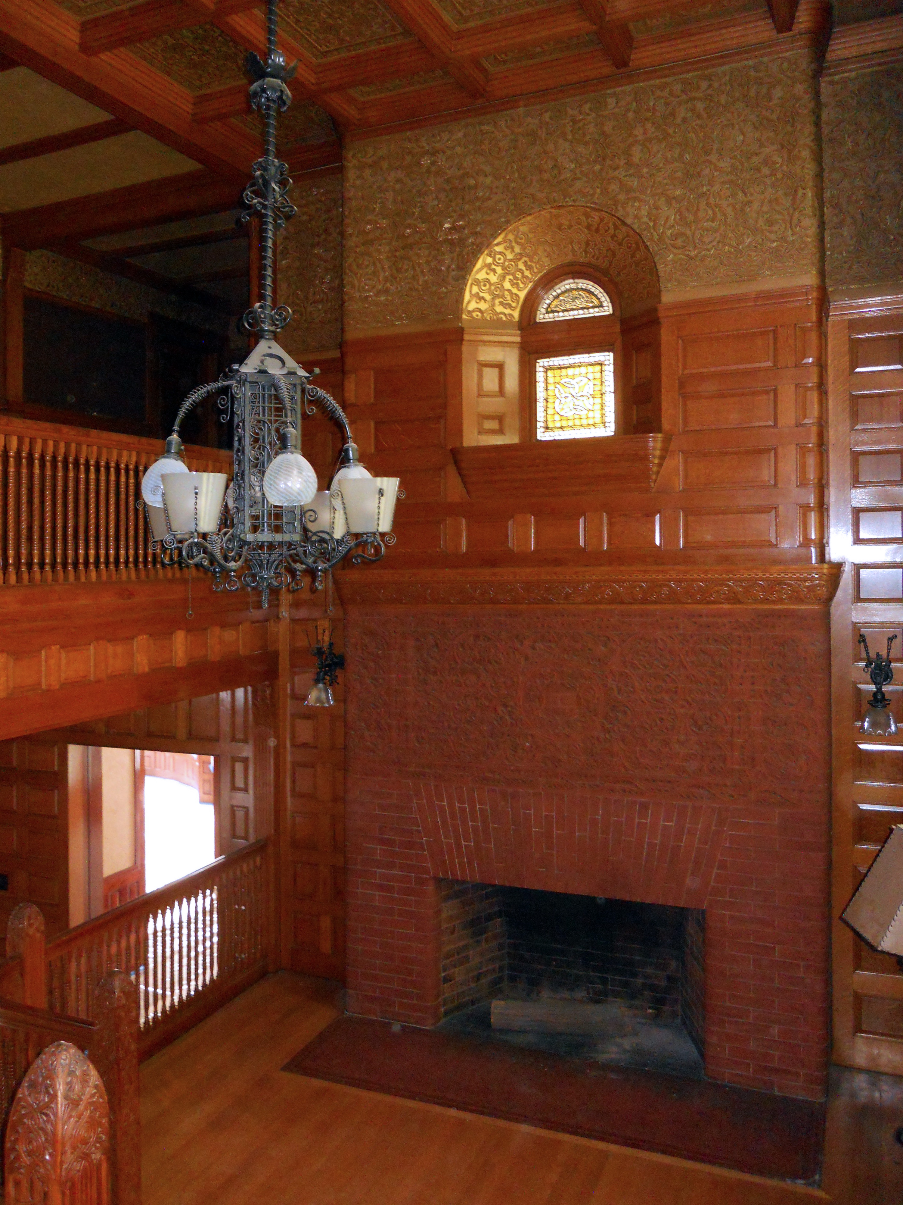
It is during this 30-year period, perhaps the heyday of the speaking tube, when the residence in Cambridge, MA, the focus of the present study, was built. Designed in 1887 by the Boston architecture firm of Hartwell and Richardson (Henry Walker Hartwell and William Cummings Richardson), the Shingle Style home is filled with exotic woods, stained glass windows, hand-stenciled ceilings, dual gas-electric light fixtures, and 10 unique fireplaces
(Figure 6 – Interior stained glass and carved woodwork)
(Figure 7 - Formal staircase and stained glass in Stair Hall)
(Figure 8 – Fireplace in Stair Hall)
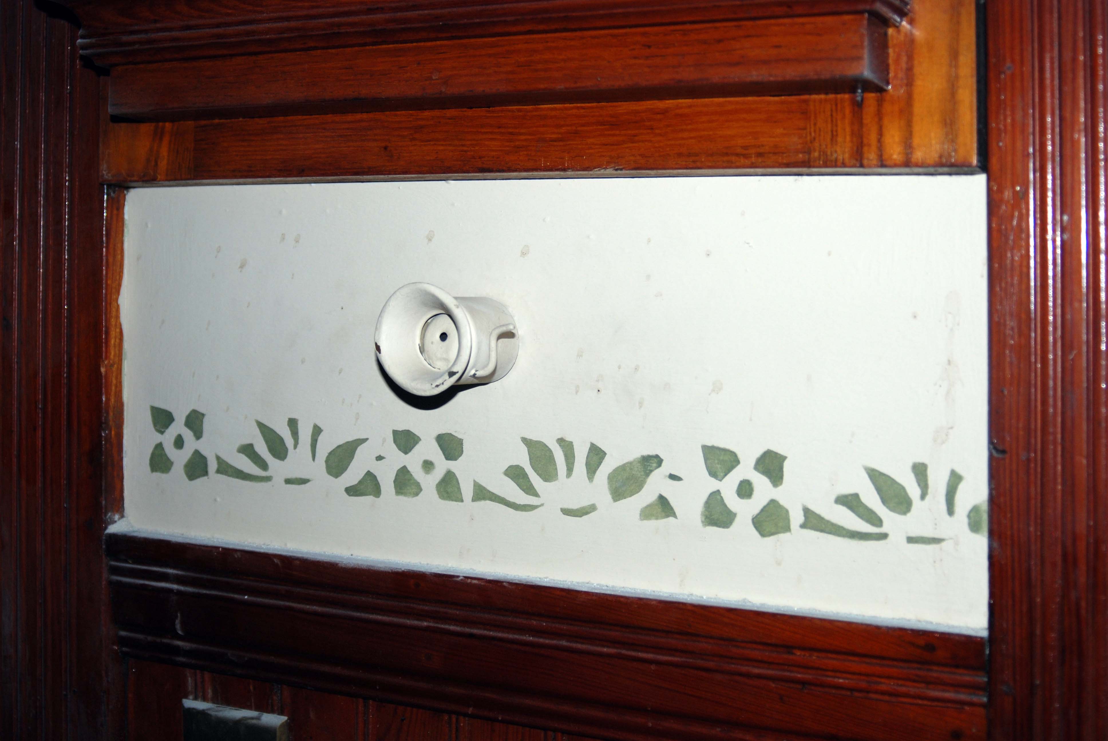
The residence also includes an electric system for alerting household staff, which is augmented by a metal speaking tube that leads from outside the kitchen pantry to the second floor corridor
(Figure 9 – Speaking tube at kitchen pantry)
(Figure 10 – Speaking tube at 2nd floor corridor)
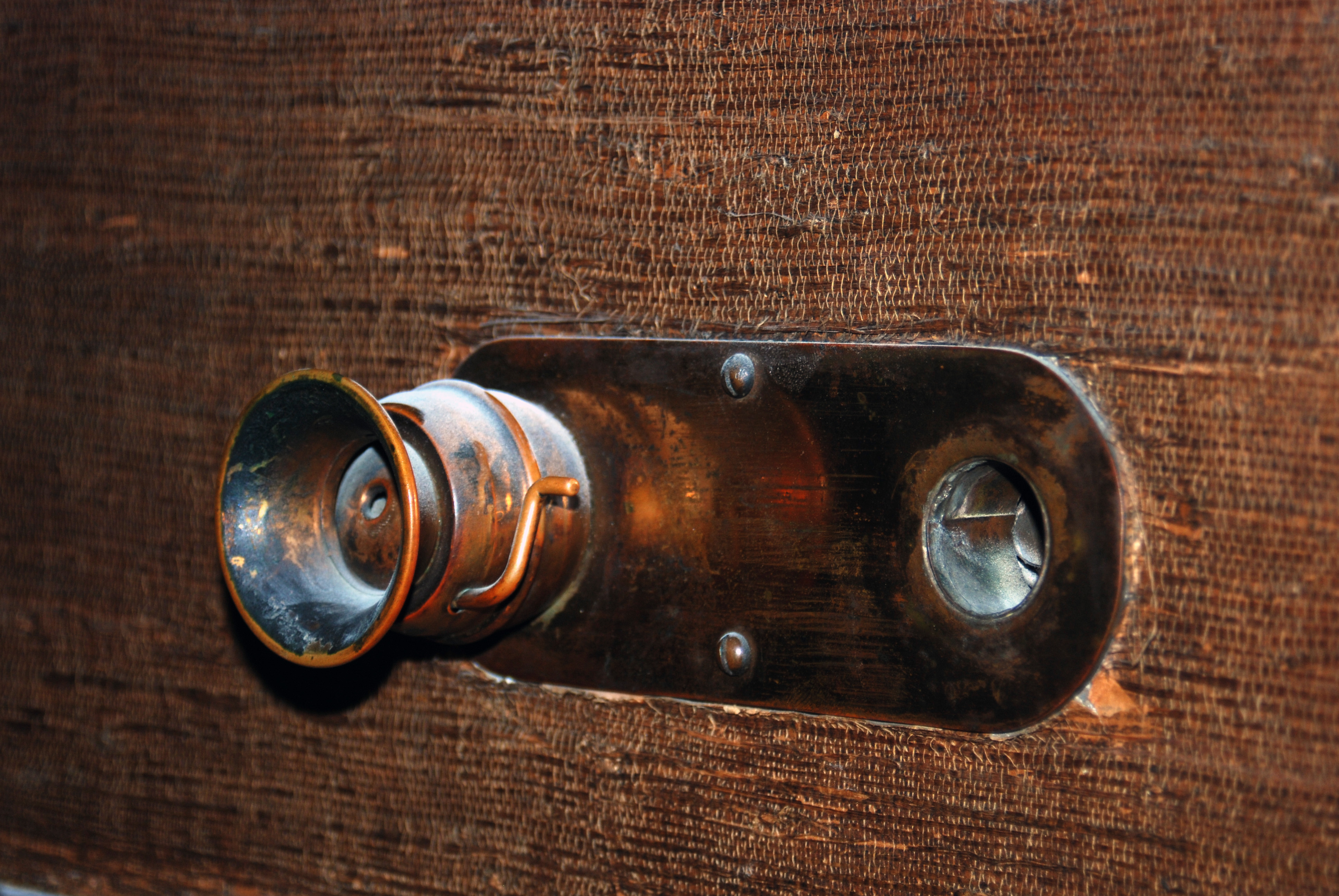
As shown in Figures 9 and 10, each end of the speaking tube is covered by a whistle valve. This valve would remain closed covering the speaking tube until a person opened it at one end and blew through the tube. The tea kettle-like whistle on the other end would sound and alert people nearby that verbal communication was requested. The person on the whistling end would then open his/her valve and converse through the tube. It appears that two speaking tubes once terminated at the second floor corridor, however, no other connection was found in the home other than that connecting the kitchen pantry and the 2nd floor.
The flared opening shown in Figures 9 and 10 on the ends of the speaking tube increases the efficiency of sound radiation. The flared opening, or horn, eases the transition of sound into the tube from the mouth, and similarly, out of the tube to the ear. This transition or coupling between sound at the mouth of the horn and sound within the tube results in an effective increasing of the area that is radiating sound at the listening end of the tube, making the radiation of sound energy to the listener’s ear much more efficient.
The “acoustic telegraph” or speaking tube did not decrease from use as quickly as one might expect with the widespread use of electricity and the development of more sophisticated telephone and microphone technology in the early 20th century. An article in Time magazine from 1938 mentions a rather clever use of an existing speaking tube by the world-famous late Romantic composer, Richard Strauss. At the entrance to the 5-acre estate, beside the iron gate was a “push-bell” and a speaking tube. Unwanted visitors were not aware that the speaking tube was connected to a phonograph 50 yards away in the servants’ quarters. When the push-bell was pressed the pre-recorded message “Dr. Strauss is not at home” would be broadcast through the speaking tube. Close friends knew that a second ring would stop the record and open the gate.
The speaking tube did not only see domestic use, but military use as well. Its ability to function reliably without the need for any power source other than the human voice resulted in the installation of speaking tubes on naval vessels, as a back-up to electronic communication systems, well into the mid 20th century.
2Elementary Treatise on Physics, Experimental and Applied for the Use of Colleges and Schools. Ganot, Adolphe; trans. Edmund Atkinson. W. Wood and Company, 1877.
3U.S. Patent No. 540529. Electrically-controlled Speaking-tube, 1895. George S. Williamson.
4U.S. Patent No. 186787. Improvement in Electric Telegraphy, 1877. Alexander Graham Bell.
Tests & Procedures
Speaking tubes are a type of what is known as a wave guide. Waveguides may carry electromagnetic signals (microwave oven) or acoustical signals (stethoscope, speaking tube, or metal ventilation duct). The dimensions of a waveguide and the nature of the interior walls put specific conditions on which wave frequencies will travel (and how they will travel) from one end of the waveguide to the other. This opportunity to test a residential speaking tube provides some technical insight into why speech is intelligible when heard through a speaking tube, and compares sound measured through a speaking tube with existing metrics that rate the quality of speech intelligibility.
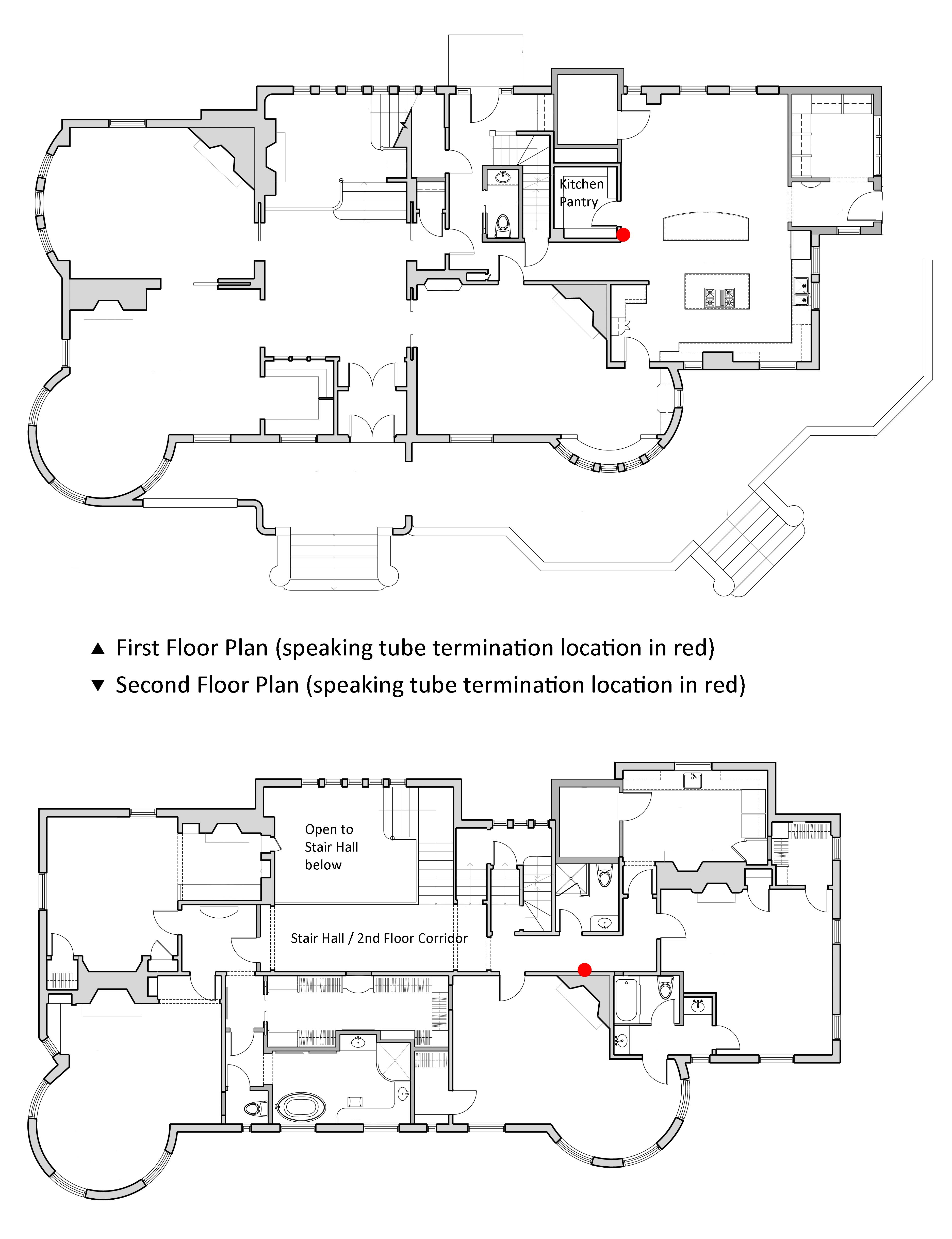
The speaking tube measured in the Cambridge, MA residence is approximately 17 feet, 9 inches long (5.41 m), and connects the kitchen pantry on the first floor to the second floor corridor
(Figure 11 – 1st and 2nd Floor Plans with indicated speaking tube locations)
A small desktop computer loudspeaker was used as the sound source, and positioned very close to the flanged opening of the speaking tube to approximate the location where the person’s mouth would be located. A microphone was placed at the other end of the speaking tube with the capsule even with the flared opening to approximate the location of the ear when the tube is in use.
(Figure 12 – Microphone at 2nd floor corridor speaking tube)
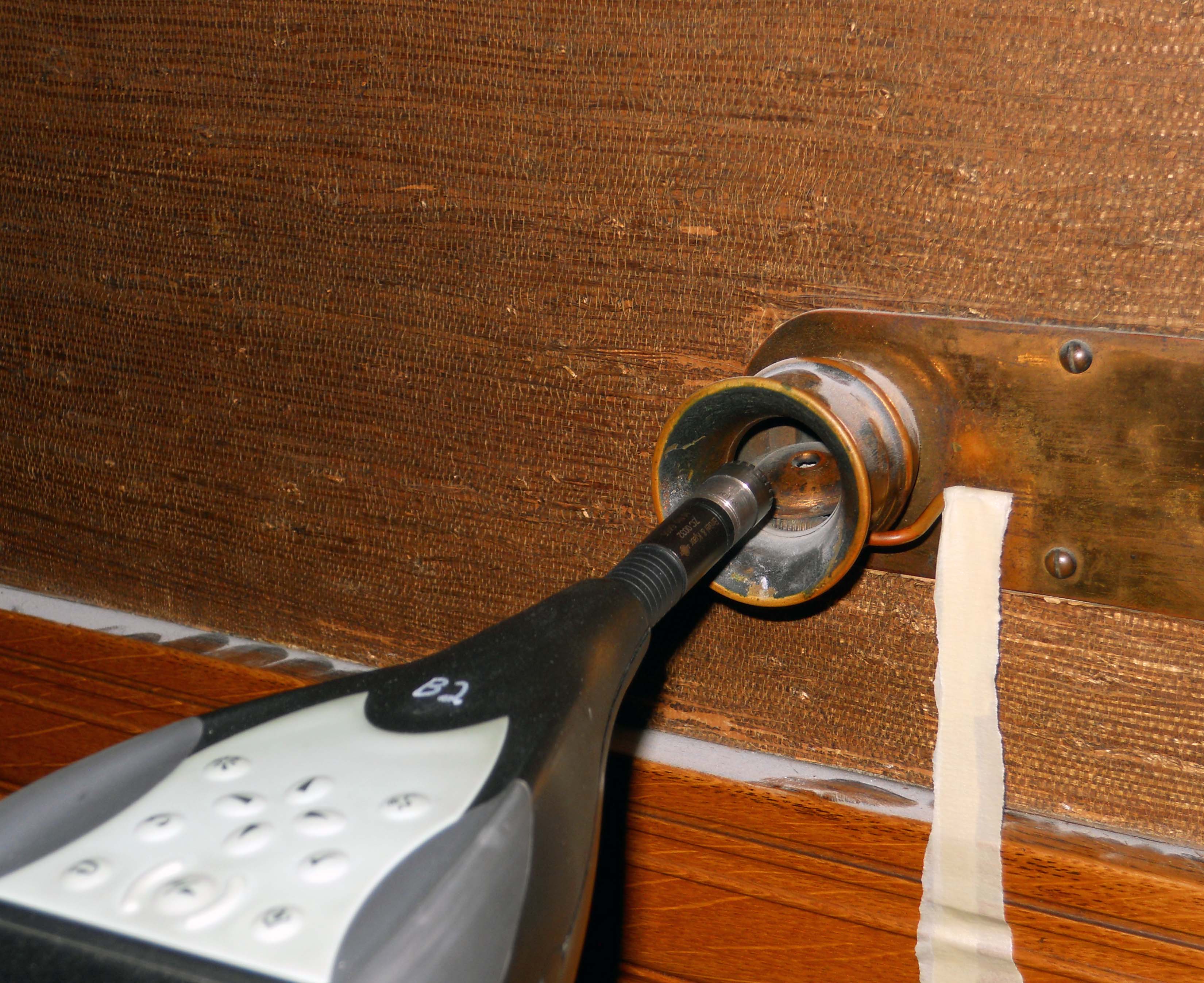
The microphone was connected to the same computer which provided the broadband pink noise to the loudspeaker; pink noise is a powerful tool in acoustical testing because it contains equal sound energy in every octave, and it facilitates testing the behavior of all audible frequencies of sound simultaneously.
The test setup was used to examine sound propagation at specific frequencies in the speaking tube, this was then compared with frequencies inherent to speech that are significant for good intelligibility
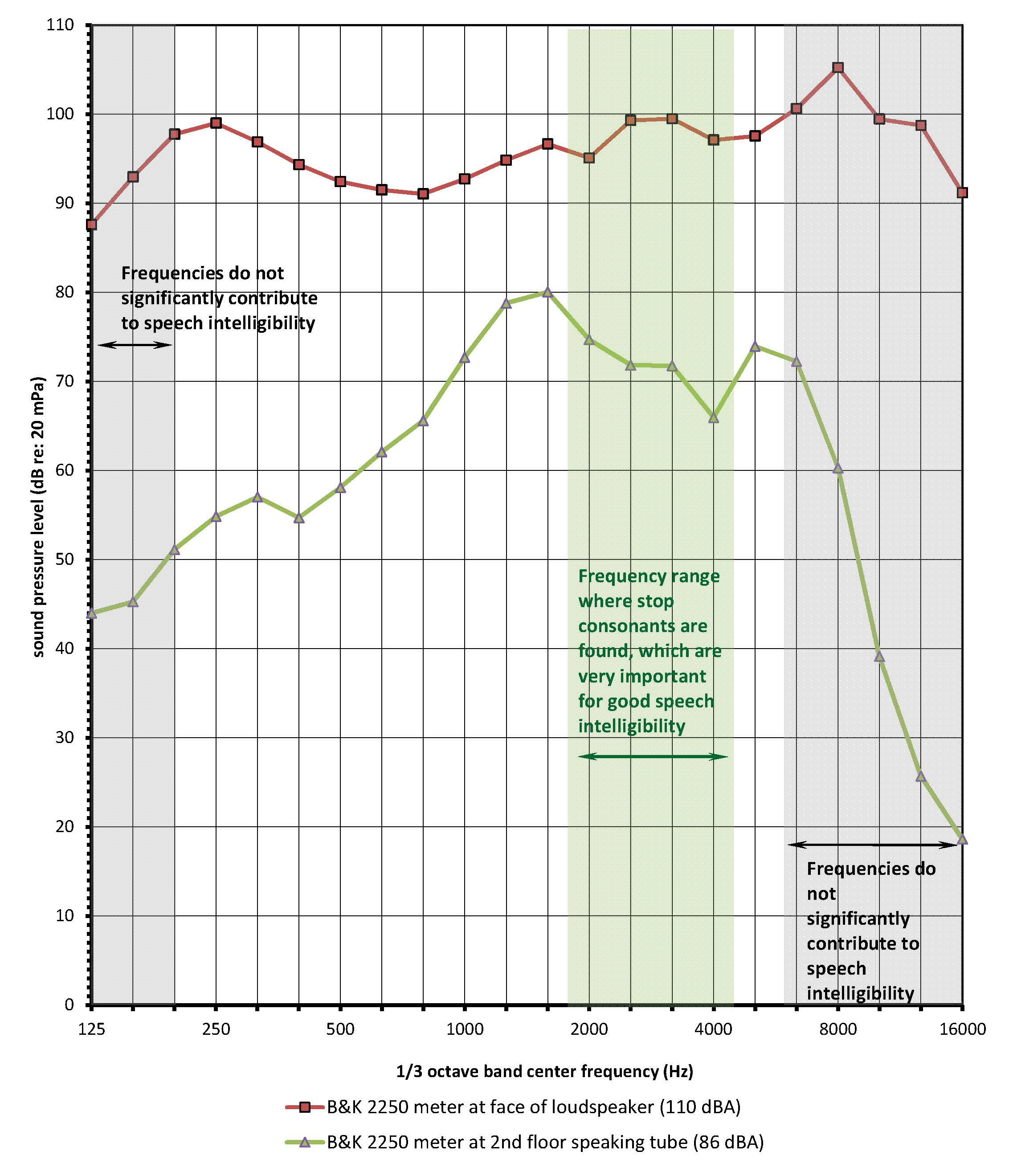
(Figure 13 – Measured sound source and receiver sound levels)
(Figure 14 – Frequency ranges for common sounds)
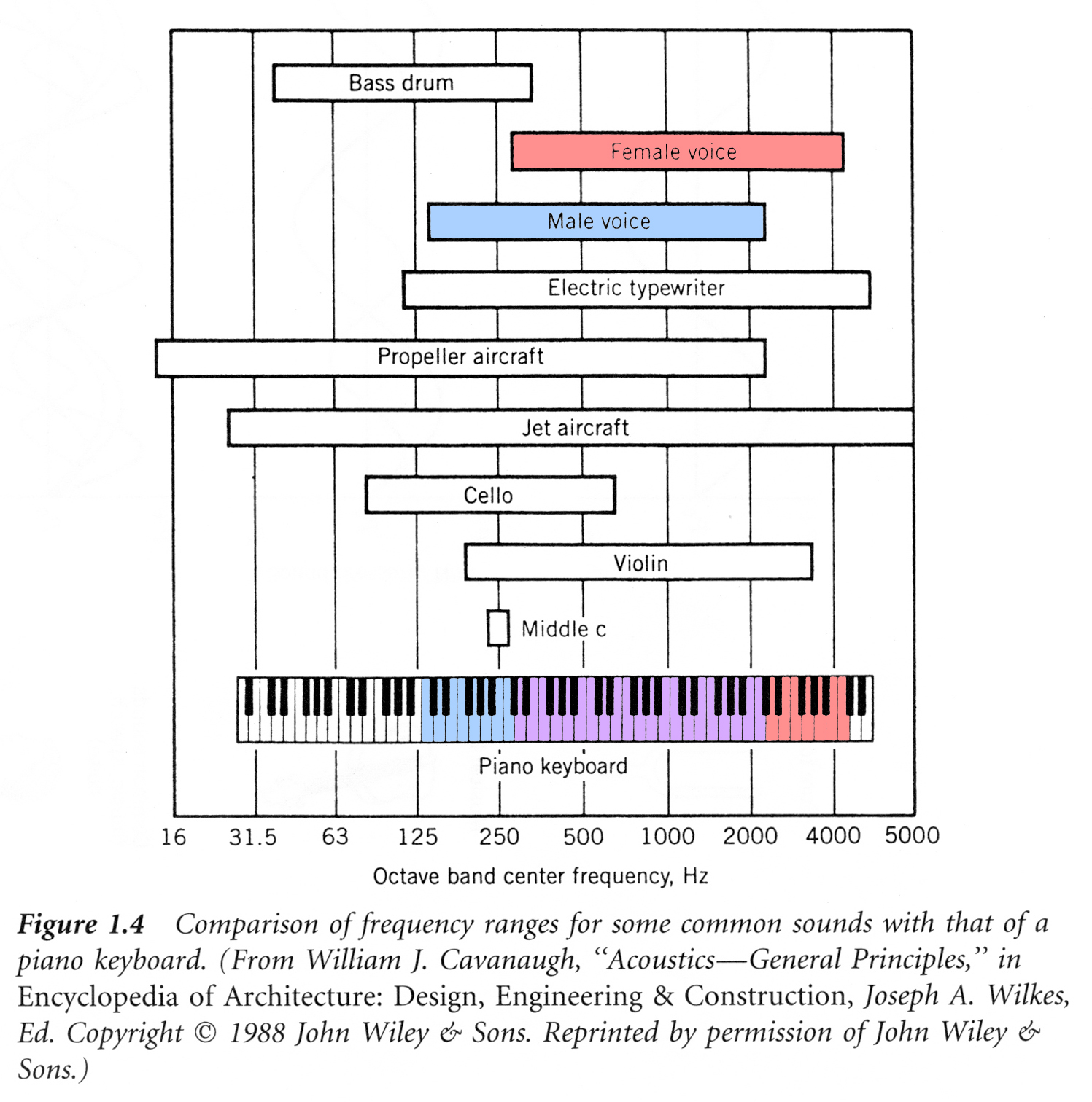
The typical range of frequencies for male and female voices is shown in Figure 14 and compared with the typical range of frequencies for other sound sources. The shape of the transmitted sound spectrum is ultimately determined by the transfer function of the speaking tube; the transfer function reflects the unique conditions which the size, length, and boundary (wall surface) properties place on the sound waves traveling through the tube. As shown in Figure 13, the sound levels measured at the opposite end of the tube from the loudspeaker are higher in the 200 Hz to 5000 Hz range than at very low or very high frequencies. Within the 200 Hz to 5000 Hz frequency range is a smaller frequency range between 2000 Hz and 4000 Hz where stop consonants are found; stop consonants (sounds produced by speaking the letters p, b, or t) are very important for good speech intelligibility. Figure 15 examines the difference between the sound level produced atthe loudspeaker and that measured at the opposite end of the speaking tube.
(Figure 15 – Sound level change from one end of the speaking tube to the other)
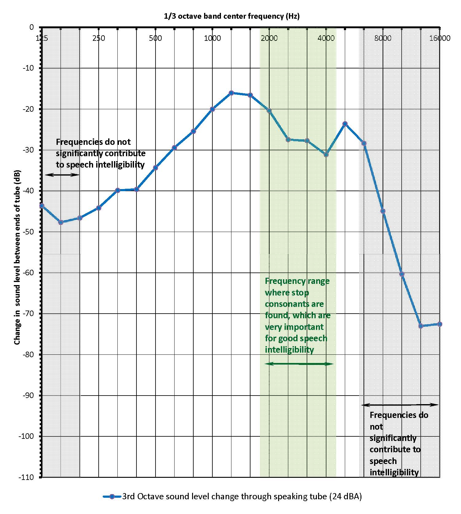
In this figure, a higher value at a given frequency indicates a greater amount of sound is transmitted from the speaker to the microphone through the tube.
Aside from frequency content, total sound level (i.e. the sound pressure level or Lp) is also important for intelligibility; a certain sound pressure level is needed so speech can be heard above other sounds in the environment. The average sound pressure level of speech measured within 3 inches (7.62 cm) of the mouth is approximately 75 to 80 dBA. However, it is the maximum sound pressure levels in human speech that are important for intelligibility, and these maxima are at least 10 dBA greater than the average sound level. The speaking tube measured in this investigation has an overall reduction in sound level of approximately 25 dBA from one end of the tube to the other, therefore maxima of 85 to 90 dBA would be approximately 60 to 65 dBA at the other end of the tube (the total reduction in sound level is approximately 25 dBA through the tube, but at speech-critical frequencies the reduction in level is as low as 15 dB). Someone speaking very close to the horn of this speaking tube produces average sound levels at the other end between 50 and 55 dBA, with maximum speech sound levels between 60 and 65 dBA. Sound at these levels is more than adequate to achieve a good signal-to-noise ratio for speech intelligibility at the listening end of the tube.
A specific speech intelligibility parameter was also measured through the speaking tube. The speech transmission index (STI) is a single number metric ranging from 0 to 1 that characterizes speech intelligibility, with a STI = 1 being very intelligible and STI = 0 being unintelligible. Like the shape of the frequency spectrum measured at the second floor (see Figure 13), the measured STI value is influenced by the size, shape, and boundary conditions that the speaking tube possesses. A simplified method of measuring STI is known as STIPA. The STIPA measurement involves the use of a source signal whose frequency characteristics are similar in nature to those found in speech. STIPA measurements were made for three conditions:
These measurements were conducted both with the loudspeaker at the first floor location and at the second floor location. The summarized results are shown in Figure 16
(Figure 16 – STI-Pa values for selected testing conditions)
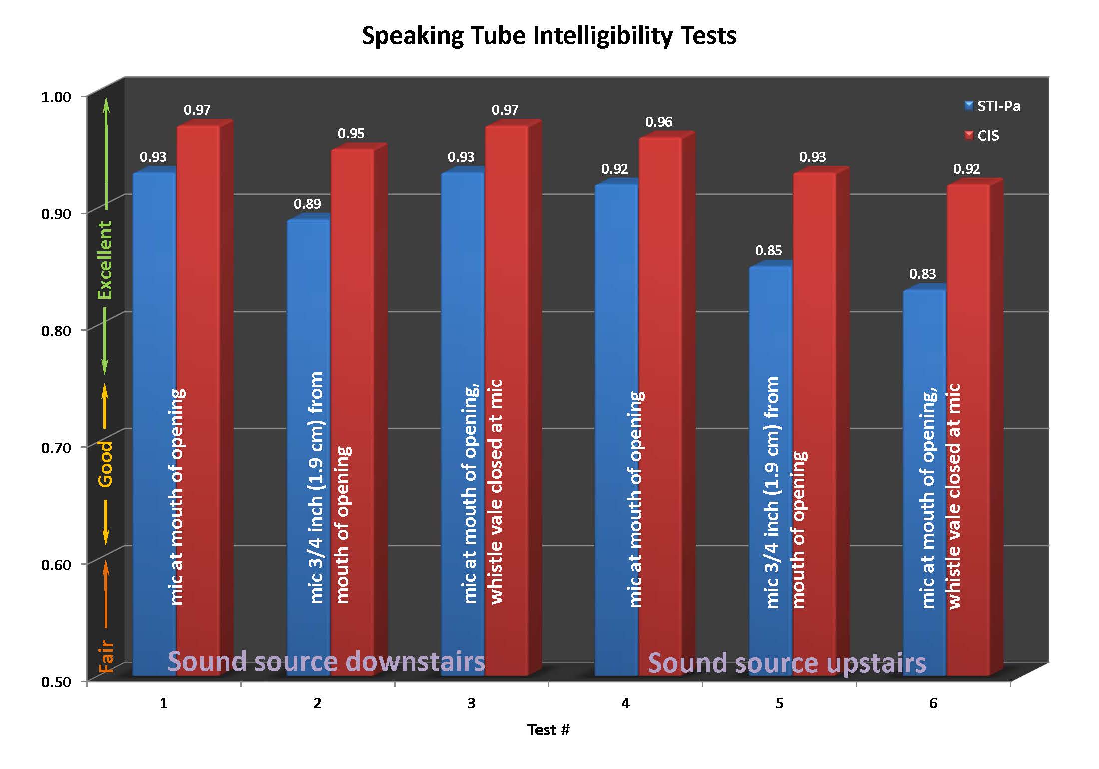
Values for another speech intelligibility metric, the common intelligibility scale (CIS) are also given for each test. As shown in Figure 16, a noticeable decrease in intelligibility resulted from moving the microphone a small distance away from the flared opening/horn of the speaking tube.
Conclusion
The speaking tube measurements indicate a strong transmitted sound signal in the 200 Hz to 5000 Hz frequency range, which coincides with the range of frequencies that are significant contributors to good speech intelligibility. The geometry of the tube itself, i.e. its small diameter and rigid walls, effectively creates an acoustic filter that allows mid-range frequencies to propagate through the tube with significantly less attenuation than very low or very high frequency sound. The excellent STIPA testing results provide yet another quantitative confirmation of why this means of communication was desired in distinguished homes and businesses of the 19th century. You need not own an historic home to experience this high level of speech intelligibility through a speaking tube, however, for one might be as close as your school or neighborhood playground
(Figure 17 – Playground speaking tube)