Jayanta Panda – jayanta.panda-1@nasa.gov
Aerospace Engineer, Experimental Aero-Physics branch
NASA Ames Research Center,
Moffett Field, CA 94035
Robert N. Mosher
Aerospace Engineer
NASA Langley Research Center
Hampton, VA 23681
Barry J. Porter
Research Engineer, Aerospace Computing, Inc,
Mountain View, CA 94035
Popular version of paper 2pNS2
Presented Tuesday afternoon, December 3, 2013
166th ASA Meeting, San Francisco
The loud noise during lift-off is memorable to anyone witnessing a rocket launch (audio clip from Antares launch). The same noise is of concern to the vehicle designers, and the satellite and other payload providers. The pressure fluctuations are a major contributor to the vibration environment to which every payload, vehicle structure, propellant storage and handling device, and electronics and navigational component have to be designed, tested, and certified. Even a couple of decibel reduction of the acoustic level translates into a sizable reduction of the cost of certification and operation, and the weight of the vehicle. An important factor for any launch pad design is to reduce the noise levels via various acoustic suppression systems, such as by spraying a large quantity of water at different locations. The bellowing cloud of white gas seen during a rocket launch is mostly steam generated from the evaporation of this water. Typically, single microphones are placed at different locations on a launch pad to measure sound levels. Such microphones, however, are unable to determine the noise sources, and in turn are unable to guide a designer looking for improvements to the pad operation. In contrast, a phased array of microphones, along with beam-form processing, is capable of identifying the location and strength of the noise sources. The phased-array technology has been in use for many decades; however, the present application on a full-scale launch vehicle is new.
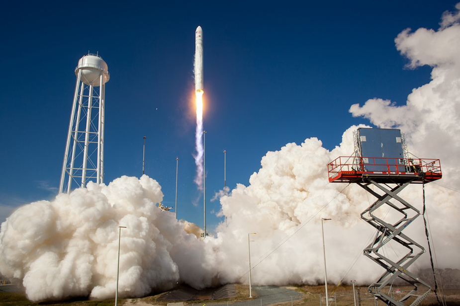
A microphone phased array works by the same principle as that of sonar and radar phased array. A large number of microphones are placed over an area to detect the curvature of the sound waves. This curvature and sound levels are used to determine the strength and direction from where the waves originated. We have designed and built a large microphone phased array for use during the first launch of the Orbital Sciences' Antares rocket. The rocket was launched from the newly built pad 0A of Mid-Atlantic Regional Spaceport located at NASA Wallops Flight Facility (Fig. 1). The array box, containing all sensors, was placed 400 feet away from the pad and was hoisted on a scissor lift 40 feet above the ground. It used 70 condenser microphones and two video cameras that operated in the visible and long infra-red wavelengths (Fig . 2). The infra-red camera was capable of viewing through steam to determine the path of the rocket exhaust. New data processing software were developed to perform beamforming for the transient noise sources. Data collected from this effort provided remarkable insight into acoustic sources not previously available.
The present effort is a continuation of the prior work [1] where a smaller size microphone phased array was used in model-scale tests. The goal of the present work is to take the phased array development to the next level, i.e., application to a full-scale rocket vehicle. The only prior application of a set of microphones used for beamforming during an actual rocket launch was by Gély et al [2]. They attached 12 microphones distributed around the large payload fairing of the Ariane V vehicle during one of its first launches. The present work differs significantly from the prior efforts. Far more insights are obtained by an optimized planar array which was placed on the launch pad rather than on the flight vehicle.
RESULTS FROM ANTARES A-ONE LAUNCH (LAUNCHED APRIL 21, 2013):
Antares is a two-stage, medium class (5000 kg) commercial launch vehicle, built and operated by Orbital Sciences Corporation. The first stage comprises twin NK-33 (AJ-26) based liquid oxygen and kerosene engines, and the second stage is a single solid motor. The vehicle was mounted on the top of a launch mount and above a duct that carried the hot plumes from the engine exhaust away from the vehicle. After ignition the engines came to full power in two seconds when the rocket's gantry was released and the vehicle lifted off the pad. The gantry, also called as the Transporter Erector Launcher (TEL), was used to erect the rocket. At launch, TEL was tilted back and the vehicle pitched away to avoid re-contact. This "TEL avoidance maneuver" significantly contributed to the noise sources.
To determine the time evolution of the noise sources, the microphone signals were divided into 0.2 s-long segments and the beamforming process was applied to each segment. A time-lapsed movie was created by joining the image maps, and can be seen here. Fig. 3 is from three frames of this movie showing the primary sources. The right column of Fig. 3 is from a high speed camera (courtesy of NASA KSC imaging group) that provided an excellent view of the launch events. Each image in the left column is a composite of the beamformed noise map whose levels are shown in the color scale, and a temperature map from the IR camera (levels not shown).
The locations and strengths of noise sources were found to change rapidly over the launch sequence. During engine ignition the launch mount was the source. As the engine came to full power, and a hot plume came out of the duct, the exit face of the duct was found to be the most prominent source (bottom row of Fig. 3). Effective cooling by water sprayed inside the duct limited the extent of this source and kept the acoustic levels to a reasonable value. As Antares started to elevate, it tilted east (towards the ocean) and drifted away from the duct hole as a part of a TEL avoidance maneuver. This caused the hot plume to spread over the pad. A large region on the top of the pad became a loud noise source (mid row of Fig. 3). Further elevation of the vehicle was accompanied by another water system that sprayed on the top of the pad and reduced the extent of the on-pad source. As more and more of the plume emerged out of the hole, the plume itself became the noise source - neither the duct exhaust nor the top of the pad were significant sources (top row of Fig. 3). Based on the insights gained from the phased array effort, the timing for the water spray will be changed for an earlier start for the next launch of the Antares vehicle.
Fig. #1: Phased array (right hand side, on scissor lift) during Antares A-one launch.
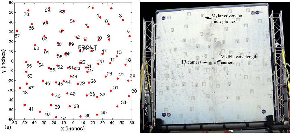
Fig. #2: Microphone layout (left), and a photograph of the front surface of the 10-ft X10-foot array (right).
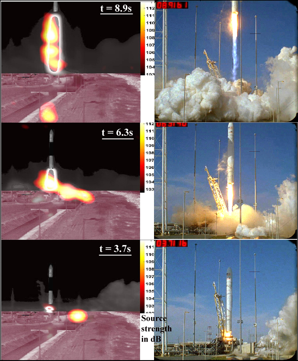
Fig. #3: Left column: Noise maps superimposed on frames from IR camera, conventional beamform at 2 kHz. Right column: Corresponding frames from a high-speed camera.
References:
[1] Panda, J. & Mosher, R. "Microphone Phased Array to Identify Liftoff Noise Sources in Model-Scale Tests," J. Spacecraft & Rockets, Vol. 50, No. 5, September-October 2013.
[2] Gély, D., Elias, G., Bresson, C., Foulon, H., Radulovic, S, 2000 "Reduction of supersonic jet noise. Application to the Ariane 5 launch vehicle," AIAA paper 2000-2026, 6th AIAA/CEAS Aeracoustics Conference, Hawaii.