Popular version of paper 2aEA1
We are all too familiar
with the loud SCREECH!!! that can
happen in a public address system when the microphone is placed too close
to the loudspeaker. Unfortunately, the same thing can happen in a hearing
aid. After all, a hearing aid contains a microphone and a loudspeaker connected
by a high gain amplifier and the distance between the microphone and speaker
is very small. The people and companies who design and fit hearing
aids must pay constant attention to minimizing the sound from the speaker
that is able to pass from the ear canal back to the microphone.
However, there is
another way that energy from the speaker can get to the microphone to provide
the feedback needed to start a screechy oscillation. All loudspeakers generate
at least a small amount of vibration as an unintended consequence of their
operation. If this vibration is transferred to the hearing aid shell, it may
generate a small amount of sound that is sensed by the microphone. The possibility
of feedback from this vibration is much greater in a hearing aid than in a
public address system, because the microphone and speaker are connected to
each other through the case of the hearing aid. For decades, hearing aid manufacturers
have needed to be very careful in the way the microphone and speaker are mounted
into the case to minimize the possibility that vibration feedback could cause
an oscillation.
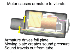
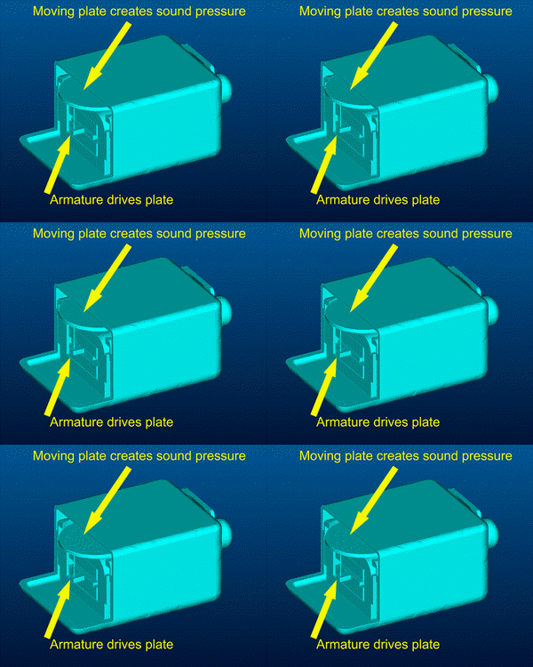
Inside the receiver,
the moving plate is pushed by a thin iron armature, that in turn, is pushed
by the magnetic field generated by an electrical current from the amplifier.
To understand why the receiver generates vibration, the important thing to
notice is that the foil plate that generates the sound and the iron armature
that drives it are moving together. They move back and forth together, both
of them always moving in the same direction at any given time. The first thing that
must be done to balance the forces is to make the mass of the moving plate
equal to that of the armature. This means that a lot of mass must be added
to the foil plate, since it is normally much lighter than the iron armature.
(The thickness of the armature cannot be decreased, as this would significantly
reduce the acoustic output available from the device.) The simple addition
of mass to the plate works well at low frequencies, but by itself is not sufficient
at higher frequencies. The reason is that, at higher frequencies the plate
does not remain completely rigid, but bends a little as it vibrates. At some
higher frequency, the plate has a bending resonance in which different parts
of the plate move in opposite directions. For all frequencies near to and
above the frequency of the first bending mode resonance, where the plate does
not move as a rigid mass, it does not properly balance the vibration of the
armature. The early prototypes of the design worked quite well for frequencies
below 1000 Hz, but had even greater vibration than the conventional receiver
for frequencies above 3500 Hz.
We expect that this
vibration-balanced receiver will have advantages for both hearing aid manufacturers
and users of hearing aids. For manufacturers, the advantage should be easier
and quicker methods of manufacturing, since less attention need be given to
isolating the receiver vibration from the hearing aid shell. For the user
of hearing aids, the objective is aids built with the new receiver will have
less of a tendency to screech.
Of course it would
be wonderful if we could conclude that this new receiver will eliminate all
problems related to screeching hearing aids. That is unfortunately not the
case. There are other forms of feedback than vibration, and those require
different kinds of solution. Much work has been done by others in recent years
on the general problem of feedback reduction in hearing aids, and progress
is being made on several fronts. The vibration-balanced receiver will work
well in concert with these other feedback reduction methods. It is realistic
to expect that the combination of this new receiver with other feedback reduction
methods that have become available will make a substantial improvement in
the products available to hearing impaired people.
David E. Schafer - david.schafer@knowles.com
Mekell Jiles, Thomas E. Miller, Stephen C. Thompson
Knowles Electronics, LLC
1151 Maplewood Drove
Itasca, Illinois 60564
For a printable version of this paper, click here (Requires
Adobe Acrobat Reader)
For further information, please contact Steve.Thompson@knowles.com
Presented Tuesday morning, December 3, 2002
First Pan-American/Iberian Meeting on Acoustics, Cancun, Mexico
 The reason that loudspeakers generate vibration
is that they contain moving parts. Their intended purpose is to generate sound,
which is a pressure wave in the air. To do this, they have a large surface
that oscillates quickly and pushes the air in front of it to create the sound
pressure. In auto and home stereo systems, this surface is the cone-shaped
surface of the loudspeaker. In a hearing aid, the moving surface is a thin
foil plate inside a component called the "receiver" that is buried inside
the hearing aid shell. The moving foil plate produces a sound pressure inside
the receiver, and this sound travels to the ear canal through a small tube.
 Newton's
Third Law of Motion says that "for every action, there is an equal and opposite
reaction." In this case it means that the force needed to move the foil plate
and armature must be balanced by an equal and opposite force from the body
of the receiver. This reaction force causes the receiver case to vibrate,
as can be seen in the figure at the right. The receiver vibration is all too
easily transferred to the hearing aid shell. Once in the shell of the aid,
the vibration can easily travel on to the microphone. This paper describes
a new receiver design that significantly reduces the amount of vibration from
the receiver. The objective of the development is to remove the vibration
at its source, so that hearing aid manufacturers can make aids that are more
reliably free from the problems of feedback oscillation.
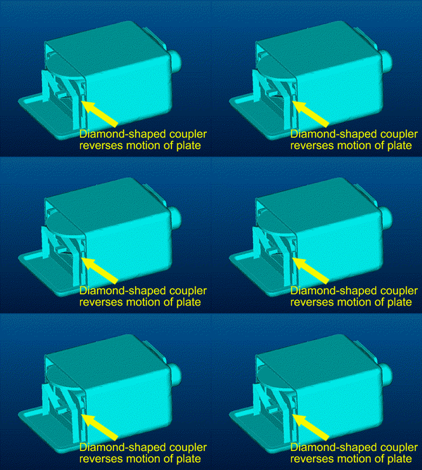
 In the old design, the motion of the armature
is simply coupled to the foil plate through a thin rod. The armature, the
rod and the plate all move together. The new design replaces the rod with
a diamond-shaped motion coupler that causes the plate to move in the opposite
direction from the armature. With the armature and plate moving in opposite
directions, the forces that they exert on the receiver case are in opposite
directions, and thus cancel. This allows the possibility of significant reduction
in vibration of the case. If the two forces can be made to be equal and opposite,
then they will cancel completely, and no vibration force would be transmitted
to the case. Notice that the receiver case in the new design to the right
does not move as does the conventional design above.
 A significant effort in the last year has been made to redesign the vibrating
plate to increase the frequency of its first bending resonance mode. In current
prototypes, this bending resonance occurs at a frequency above 10 kHz. The
graph at the right shows that the device provides an improvement over the
conventional device for all frequencies below 7 kHz, and provides at least
30 dB (a factor of 30) reduction in vibration at all frequencies below 2 kHz.
This receiver thus provides a substantial reduction in vibration at all frequencies
that are normally problematic for hearing aid feedback oscillation. A vibration
reduction of this amount has been verified in laboratory prototypes.