Samuel Chabot – chabos2@rpi.edu Jonathan Mathews – mathej4@rpi.edu Jonas Braasch – braasj@rpi.edu Rensselaer Polytechnic Institute 110 8th St Troy, NY, 12180
Popular version of 3aEA7 – Multi-user interactive systems for immersive virtual environments Presented Wednesday morning, December 01, 2021 181st ASA Meeting Click here to read the abstract
In the past few years, immersive spaces have become increasingly popular. These spaces, most prevalently used as exhibits and galleries, incorporate large displays that completely envelop groups of people, speaker arrays, and even reactive elements that can respond to the actions of the visitors within. One of the primary challenges in creating productive applications for these environments is the integration of intuitive interaction frameworks. For users to take full advantage of these spaces, whether it be for productivity, or education, or entertainment, the interfaces used to interact with data should be both easy to understand, and provide predictable feedback. In the Collaborative Research-Augmented Immersive Virtual Environment, or CRAIVE-Lab, at Rensselaer Polytechnic Institute, we have integrated a variety of technologies to foster natural interaction with the space. First, we developed a dynamic display environment for our immersive screen, written in JavaScript, to easily create display modules for everything from images to remote desktops. Second, we have incorporated spatial information into these display objects, so that audiovisual content presented on the screen generates spatialized audio over our 128-channel speaker array at the corresponding location. Finally, we have a multi-sensor platform installed, which integrates a top-down camera array, as well as a 16-channel spherical microphone to provide continuous tracking of multiple users, voice activity detection associated with each user, and isolated audio.
By combining these technologies together, we can create a user experience within the room that encourages dynamic interaction with data. For example, delivering a presentation in this space, a process that typically consists of several file transfers and a lackluster visual experience, can now be performed with minimal setup, using the presenter’s own device, and with spatial audio when needed.
Control of lights and speakers can be done via a unified control system. Feedback from the sensor system allows display elements to be positioned relative to the user. Identified users can take ownership of specific elements on the display, and interact with the system concurrently, which makes group interactions and shared presentations far less cumbersome than with typical methods. The elements which make up the CRAIVE-Lab are not particularly novel, as far as contemporary immersive rooms are concerned. However, these elements intertwine into a network which provides functionality for the occupants that is far greater than the sum of its parts.
The aim of the project carried out by a Gdansk University of Technology in cooperation with an electronics company is to conduct industrial research, development, and pre-implementation works on a new product, namely an intelligent lighting platform. This kind of street lamp system called infoLIGHT using a new generation of LEDs will become a smart city access point to various city services (Fig. 1).
The research focuses on the electronics built in the street lamp using multiple sensors (Fig. 2), including an acoustic intensity probe that measures the sound intensity in three orthogonal directions, making it possible to calculate the azimuth and elevation angles, describing the sound source position.
Figure 2 – Road lamp design
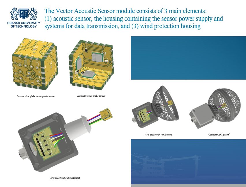
The acoustic sensor is made in the form of a cube with a side of 10 mm, on the inner surfaces of which the digital MEMS microphones are mounted (Fig. 3). The acoustic probes were mounted on the lamp posts that illuminate the roadways depending on the volume of traffic.
Figure 3 Acoustical vector sensor – construction
The algorithm works in two stages. The first stage is the analysis of sound intensity signals to detect acoustic events. The second stage analyses acquired signals based on the normalized source position; its task is to determine whether the acoustic event represents what kind of a vehicle passing the sensor and detecting its movement direction. A neural network was applied for selective analysis of traffic noise (Fig. 4). The neural network depicted in Figure 4 is the so-called 1D (one-dimensional) convolution neural network. It was trained to count vehicles passing by through the analysis of noise emitted by them.
Figure 4 Neural network applied for selective analysis of traffic noise
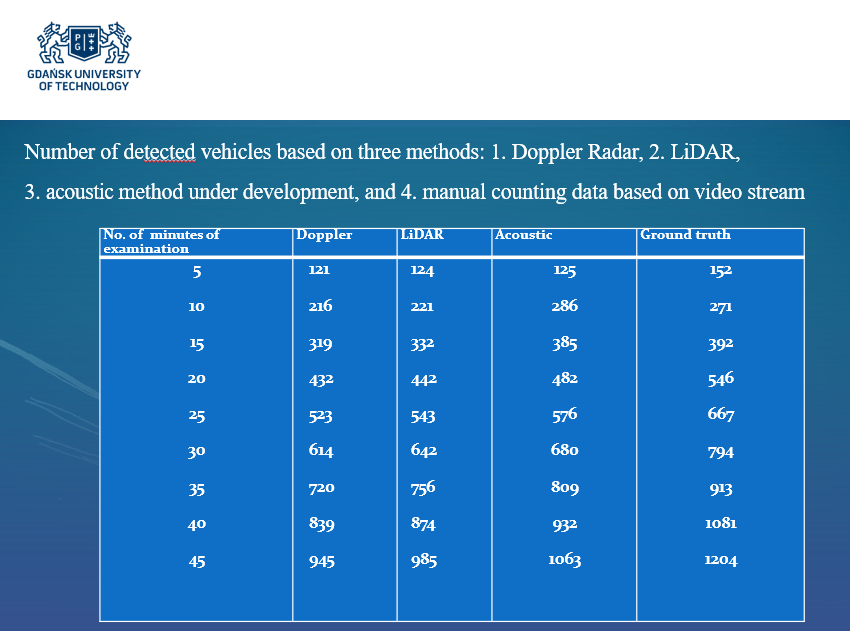
The paper presented at the ASA Meeting explains how accurately traffic can be monitored through directional noise analysis emitted by vehicles and shows the resulting application to smart cities (see Fig. 5).
Figure 5 Comparative results of traffic analysis employing various approaches
The Polish National Centre for Research and Development (NCBR) subsidizes project No. POIR.04.01.04/2019 is entitled: infoLIGHT – “Cloud-based lighting system for smart cities” from the budget of the European Regional Development Fund.
Sungtae Lee, owenlee@lgdisplay.com Kwanho Park, khpark12@lgdisplay.com Hyungwoo Park, pphw@ssu.ac.kr Myungjin Bae, mjbae@ssu.ac.kr 37-8, LCD-ro 8beon-gil, Wollong-myeon Paju-si, Gyeonggi-do, Korea (the Republic of)
This “OLED Panel Speaker” was developed by attaching exciters on the back of OLED panels, which do not have backlights. Synchronizing the video and sound on screen, OLED Panel Speaker delivers clear voice and immersive sound. This technology which only can be applied to OLED, is already adopted by some TV makers and receiving great reviews and evaluations.
With the continuous development of display industry and progress of IT technology, the display is gradually becoming more advanced. Throughout the development in display technology followed by CRT to LCD and OLED, TVs have evolved to offer much better picture quality. The remarkable development of picture quality has enabled to receive positive market reactionsIn the mean time, relatively bulky speaker was hidden behind the panel to make TVs thin. TV sound could not keep up with the progress of the picture quality, until LG Display developed Flat Panel Speaker using the merit of OLED panel thickness, less than 1mm.
To realize the technology, we developed an exciter that simplifies the normal speaker structureSpecially-designed exciters are positioned at the back of the panel, invisibly vibrate the screen to create sound.
We developed and applied an enclosure structure in order to realize “stereo sound” on one sheet of OLED panel and found positive results through vibrational mode analysis.
Depending on the shape of enclosure tape, there are Peak/Dip at a certain frequency created by standing wave. Changing the shape of peak and dip frequencies to 1/3 λ, the peak is improved by 37% from 8dB to 5 dB.
When this technology applied, the sound image moves to the center of the screen, maximizing the immersive experience and enabling the realistic sound.
Brian Kappus – brian.kappus@ultrahaptics.com Ben Long – ben.long@ultrahaptics.com Ultrahaptics Ltd. The West Wing, Glass Wharf Bristol, BS2 0EL, United Kingdom
Popular version of paper 3aEAa4 “Spatiotemporal modulation for mid-air haptic feedback from an ultrasonic phased array” presented Wednesday morning, May 9, 2017, 9 AM, Greenway D 175th ASA Meeting, Minneapolis
Haptic feedback is the use of the sense of touch in computing and interface design to communicate with a user. The average person most often experiences haptic feedback when interfacing with modern mobile devices. These uses are relatively basic: a buzz to alert the user to an incoming call or a vibration when using a touchscreen keyboard.
Interfaces enabled by gesture recognition and virtual/augmented reality, however, typically lack haptic feedback. In this paper, we present “virtual touch” technology developed at Ultrahaptics. It enables the generation of haptic feedback in mid-air, on a user’s bare hands, by the efficient creation and manipulation of ultrasonic waves (i.e. frequencies beyond the range of human hearing).
There are a variety of mechanical receptors present on the hand that are sensitive to different types of sensation including temperature, static pressure, and vibration [1]. Receptors sensitive to vibration can be stimulated through focused acoustic pressure. Ultrahaptics’ technology uses ultrasonic transducers coupled with phase delays so that the resulting interference patterns create focused acoustic pressure at focal points. The pressure is sufficient to create tactile sensations without generating audible sound.
Because the vibration-sensitive receptors on the hand are not capable of perceiving ultrasonic frequencies, to create tactile sensations the acoustic pressure then needs to be switched off and back on again (modulated) at lower frequencies – around the range of 40-400Hz.
Previous versions of this technology have been limited to discrete points of acoustic pressure which are turned on and off at the necessary frequencies to create a tactile effect [2] [3] [4]. However, another way to create the tactile effect is to move the focal point back and forth, its movement away and back again providing the modulation at a frequency perceptible by the receptors. While it is away, pressure at the starting point is low. It then returns to the starting (high) pressure when it returns. From the perspective of this starting point, the acoustic pressure varies in amplitude. This creates tactile sensations.
The technique is called spatiotemporal modulation and using it a closed curve can be repeated almost continuously, forming a robust area of stimulation instead of discrete points. Advantages of spatiotemporal modulation include the ability to render an infinite variety of curves and volumes.
Previously, spatiotemporal modulation was impractical due to the hardware computing requirements. In this paper, we present algorithms developed at Ultrahaptics that realize the required acoustic fields with a fraction of the computing power. This enables fast update rates on reasonable hardware and opens up a new class of haptics.
[Video file missing] Caption: Oil-bath visualization of spatiotemporal modulation creating 3 simultaneous shapes. Acoustic pressure is able to deform the surface of a liquid and is used to visualize the acoustic field using edge lightning. In this example, 3 shapes are traced 200 times per second to create continuous lines of pressure.
[1] S. J. Lederman and R. L. Klatzky, “Haptic perception: A tutorial,” Attention Perception & Psychophysics, vol. 71, no. 7, pp. 1439-1459, 2009. [2] T. Iwamoto, M. Tatezono and H. Shinoda, “Non-contact Method for Producing Tactile Sensation Using Airborne Ultrasound,” EuroHaptics, LNCS 5024, 504-513, 2008. [3] T. Carter, S.A. Seah, B.Long, B. Drinkwater, S. Subramanian, UltraHaptics: Multi-PointMid-AirHaptic Feedback for Touch Surfaces, Proceedings of the 26th annual ACM symposium on User interface software and technology. (UIST ’13), New York, NY, USA, 8–11 October (2013). [4] B. Long, S. A. Seah, T. Carter and S. Subramanian, “Rendering Volumetric Haptic Shapes in Mid-Air Using Ultrasound,” Transactions on Graphics (Proceedings of SIGGRAPH Asia) 33 (6) 181 (2014).
James Windmill – james.windmill@strath.ac.uk University of Strathclyde 204 George Street Glasgow, G1 1XW United Kingdom
Popular version of paper 2aEA3 Presented Tuesday morning, May 8, 2018 175th ASA Meeting, Minneapolis, MN
Miniature microphones are a technology that everyone uses everyday without thinking about it. They are used in smartphones, laptops, tablets, and more recently in smart home equipment. However, working with sound technology always means there are issues, like how to deal with background noise. Engineers have always looked for ways to make technology better, and in miniature microphones one of the paths for improvement has been to look at how insects hear. If you want to design a really small microphone, then why not look at how the ear of a really small animal works?
In the 1990’s researchers discovered that a small fly (Ormia ochracea) had a very directional ear. That is, it can tell the direction that sound was coming from with a lot higher accuracy than predicted. Since that discovery many engineers have made attempts to make microphones copying the mechanism in the Ormia ear. Much of the effort has spent been trying to get round the problem that the Ormia is only interested in hearing one specific frequency. Humans want microphones that cover all the frequencies we can hear. Why bother copying this insect ear? If you could make a tiny directional microphone then a lot of background noise drops simply because the microphone points towards the person speaking.
At Strathclyde we have developed a variety of microphones based on the Ormia ear mechanism. The main push in this work has been to try and get more sensitive microphones working across more frequencies. To do this we have put four microphones into one Ormia type design, as in Figure 1. So instead of a single frequency, the microphone works as a miniature directional microphone across four main frequencies [1].
Figure 1. Four frequency Ormia inspired miniature microphone.
Work on the Ormia system at Strathclyde encouraged us to think of other things that insect ears do, and their structure, to see if there are other advantages to find. This work has taken two main themes. Firstly, many hearing systems in nature are not just simple mechanical systems; they are active sensors. That is they change how they function depending on what sound they’re listening to. So for a quiet sound they increase the amplification of the signal in the ear, or for a loud sound they turn it down. Some ears also change their frequency response, changing the frequencies they are tuned to. Strathclyde researchers have taken these ideas and produced miniature microphone systems that can do the same thing [2]. Why do this, when you can just do it in signal processing? By making the microphone “smart” you can free up processor power to do other things, or reduce the delay between a sound arriving and the electronic signal being used.
Figure 2. Graphs showing the results of a miniature microphone actively changing its frequency (A) and gain response (B).
Secondly, we thought about how you make miniature microphones. The ones we use in phones, computers etc today are made using computer chip technology, so are made very flat out of very hard silicon. Insect ears are made of a relatively soft material, and come in a huge variety of three dimensional shapes. The obvious thing it seemed to us was to try making insect inspired microphones using 3D printing techniques. This is very early work, its not easy to do. But we have had some success making microphone sensors using 3D printers [3]. Figure 3 shows an “acoustic sensor” that was inspired by how the locust hears sound.
Figure 3. 3D printed acoustic sensor inspired by the ear of a locust.
There is still a lot of work to do, both on developing these techniques and technologies, and on working out how best to use them in everyday technologies like the smartphone. Then again, a huge number of different insects have ears, each working in slightly different ways to hear different things for different reasons, so there are a lot of ears out there we can take inspiration from.
[1] Bauer R et al. (2017), Housing influence on multi-band directional MEMS microphones inspired by Ormia ochracea, IEEE Sensors Journal, 17: 5529-5536. http://dx.doi.org/10.1109/JSEN.2017.2729619
[2] Guerreiro J et al. (2017), Simple Ears Inspire Frequency Agility in an Engineered Acoustic Sensor System, IEEE Sensors Journal, 17: 7298-7305. http://dx.doi.org/10.1109/JSEN.2017.2699697
[3] Domingo-Roca R et al. (2018), Bio-inspired 3D-printed piezoelectric device for acoustic frequency selection, Sensors & Actuators: A. Physical, 271: 1-8. https://doi.org/10.1016/j.sna.2017.12.056
Department of Otorhinolaryngology, Head and Neck Surgery Unversity of Zurich Frauenklinikstrasse 24 Zürich, 8091, SWITZERLAND
Cochlear Technology Centre Schalienhoevedreef 20 I Mechelen, 2800, BELGIUM
Cochlear AG Peter Merian-Weg 4 Basel, 4052, SWITZERLAND
Popular version of paper 2aEA6, “A MEMS condenser microphone based acoustic receiver for totally implantable cochlear implants” Presented Tuesday morning, May 8, 2018, 11:00-11:20 AM, Greenway D 175th ASA Meeting, Minneapolis
In the totally implantable cochlear implant (TICI) system, the external parts of the currently available cochlear implants (CIs) are integrated into the implant and hence, become invisible and well protected. Recipients using such a system would significantly benefit from 24/7 hearing and the overall improved quality of life that comes with an invisible hearing aid (related to playing sports, sleep comfort, reduced social stigma, etc.). A TICI system is not commercially available to date, mainly because of technical difficulties of making an implantable microphone (IM).
In contrast to an external microphone, an implantable one needs sophisticated packaging to meet stringent requirements for long term biocompatibility, safety and reliability. In addition, high sensing performance, low power consumption and simple surgical approach have to be considered during the design phase.
The goal of the present project is to develop and validate an IM for a TICI system.
Figure 1. Schematic drawing of the present concept of an IM for a TICI system. The illustration shows the main parts of the intracochlear acoustic receiver (ICAR) and their anatomical locactions. The sound receptor (SR) with up to 4 sound receiving protective diaphragms, the enclosure of the MEMS condenser microphone (CMIC) and the system for static pressure equalization (SPEQ) form a biocompatible Ti packaging structure which hermetically seals the MEMS CMIC against body tissue. The SPEQ system represents a passive adaptive volume which compensates for ambient static pressure variations and thus, provides stable sensing performance.
Our approach for an IM is a device which measures the pressure fluctuations in the cochlea (inner ear), which are induced by the outer and middle ear chain, a so-called intracochlear acoustic receiver (ICAR, Fig. 1). An ICAR benefits from the amplification and directionality cues of the ear anatomy, whilst minimizing interference by body noises. The ICAR might potentially be integrated into the existing CI electrode array and hence, such a TICI may benefit from a similar surgical procedure as applied for a CI.
The design concept for the ICAR is based on a commercially available MEMS condenser microphone (MEMS CMIC) as it is used for telecommunication devices. The MEMS CMIC of the ICAR is fully packaged in a biocompatible enclosure made out of titanium (Ti) but still enables sensing of the pressure fluctuations in the cochlea. The sensing capability of the MEMS CMIC is maintained by sealing its pressure sensing port with thin protective Ti diaphragms (PD). Sound induced vibrations of the PDs cause pressure fluctuations within the gas-filled volume formed by the PDs and the sensing element of the MEMS CMIC. Since the size of the MEMS CMIC enclosure prevents its insertion into the cochlea, only the thin sensor head carrying the PDs, called the sound receptor (SR), is inserted into the cochlea duct. The enclosure remains in the middle ear cavity adjacent to the entrance of the cochlea (Fig. 1).
Figure 2. The first prototype (PT I) of the proposed design concept of the ICAR (a). PT I uses a commercially available MEMS CMIC in its original packaging (c, top enclosure removed). An acrylic adapter interconnects the pressure port of the MEMS CMIC and the SR (fused silica capillary tube). The PD, a 1 micron thick polyimide diaphragm supported by a thin-wall cylindrical structure made out of single crystal silicon, seals the front end of the SR tube (b).
The development process of the ICAR started with a simplified version of the proposed concept. The first prototype (PT I) is not implantable and does not meet the sensing performance targeted in the final ICAR (Fig. 2). It was mainly designed to validate lumped element modelling of the sensor concept and to measure and quantify intracochlear sound pressure (ICSP) in human and sheep temporal bones, providing crucial information towards an ICAR of a TICI system [1, 2]. The data from ICSP measurements were in good agreement with results in the literature [3].
Figure 3. Prototype II (PT II) combines the SR from PT I and a custom-made Ti enclosure for the MEMS CMIC with optimum form factor for surgical insertion (b). The flexible interface between microphone and the amplifier unit simplifies surgical insertion and sensor fixation (a). A flexible printed circuit board (FCB) enables packaging of the MEMS CMIC and the corresponding ASIC unit in an enclosure with optimum form factor. In addition, it simplifies electrical interfacing due to an integrated FCB cable (c).
As the next step, the second ICAR prototype (PT II) was designed and built such that surgical insertion into the cochlea was possible during acute large animal experiments. In PT II, a custom-made Ti enclosure for the MEMS CMIC was combined with the SR of PT I (Fig. 3). A flexible interface between the microphone and the external amplifier unit allows surgeons to insert and fix the sensor without using complex assisting tools (e.g. micro-manipulator). The acute large animal experiments revealed that the presented ICAR concept is a suitable receiver technology for TICI systems.
Figure 4. CAD model of prototype III (PT III) of the ICAR combining the MEMS CMIC enclosure from PT II and a Ti SR with four 1 micron thick Ti diaphragms. The SR structure and the enclosure are laser welded together. The multi-diaphragm SR design is required to meet the targeted sensing performance (sensitivity, bandwidth). The micro-channel within the SR pneumatically interconnects the PDs and the MEMS CMIC.
Currently, a fully biocompatible ICAR (PT III, Fig. 4) is under development. PT III, which is planned to be used for chronic large animal tests, is expected to fulfill all requirements for application of the ICAR to a TICI system, including high performance, low power consumption and good system integration. The key feature of PT III is the Ti SR with four PDs instead of one as used in PT I and PT II. It is fabricated from thin Ti sheets which are structured by photo etching and hermetically joined by diffusion bonding. The 1 micron thick PDs are deposited onto the bare SR structure using DC magnetron sputtering on top of a low temperature decomposable polymer material (Fig. 5).
Figure 5. Tip region of the Ti SR of PT III after DC magnetron sputtering of a 1 micron thick Ti layer on both sides of the SR (picture from the first diaphragm fabrication trial on the multi-diaphragm SR structure design).
Acknowledgements This work was supported by the Baugarten Stiftung Zürich, Switzerland, by the Cochlear Technology Centre Belgium and by Cochlear AG, European Headquarters, Switzerland.
[1] F. Pfiffner, et al., “A MEMS Condenser Microphone-Based Intracochlear Acoustic Receiver” IEEE Transactions on Biomedical Engineering, 64, pp. 2431-2438, 2016
[2] D. Péus, et al., “Sheep as a large animal ear model: Middle-ear ossicular velocities and intracochlear sound pressure” Hearing research 351, pp. 88-97, 2017
[3] H. H. Nakajima, et al., “Differential intracochlear sound pressure measurements in normal human temporal bones” J Assoc Res Otolaryngol 10(1) pp. 23-36, 2009


 Haptic feedback is the use of the sense of touch in computing and interface design to communicate with a user. The average person most often experiences haptic feedback when interfacing with modern mobile devices. These uses are relatively basic: a buzz to alert the user to an incoming call or a vibration when using a touchscreen keyboard.


