1pEAa5 – A study on a friendly automobile klaxon production with rhythm

SangHwi Jee- slayernights@ssu.ac.kr
Myungsook Kim
Myungjin Bae
Sori Sound Engineering Lab
Soongsil University
369 Sangdo-Ro, Dongjak-Gu, Seoul, Seoul Capital Area 156-743
Republic of Korea

Popular version of paper 1pEAa5, “A study on a friendly automobile klaxon production with rhythm”
Presented Monday, December 04, 2:00-2:15 PM, Balcony N
174th ASA meeting, New Orleans

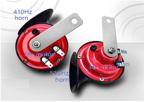
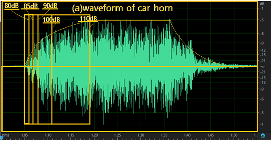
Cars are part of our everyday lives and as a result, traffic noise is always present when we are driving, riding as a passenger or walking down the street. Among the traffic noise, blaring car horns are among the most stressful and unpleasant sounds. Impulse noises, like those experienced from honking traffic horns can lead to emotional dysregulation or emotional hyperactivity of the driver and potentially cause an accident. While impulse sounds may be dangerous, the risk of avoiding car horn use altogether can be just as deadly. Not using horn sounds prevent us from informing pedestrians or other drivers of a potential accident. Although it is an important means of informing the pedestrians and other drivers of a present crisis, until now, car horn sounds and their impact on the listener have not been heavily studied. Generally, the Klaxon electromechanical car horn is a simple mechanical structure, which is excellent in durability and ease of use. However, once it is attached, it can’t change the tone of the horn sound or redesign the sound pressure size. Therefore, in this study, the width of power supply time of Klaxon was adjusted to 5 (0.01s, 0.02s, 0.03s, 0.06s, 0.13s). Then, the sound level of the Klaxon sound was set to 5 sound levels (80dB, 85dB, 90dB, 100dB, 110dB). The experimental result shows that the maximum sound pressure (pmax = 110dB) after operating the Klaxon is tmax.

Equation 1: Ps (dB) = 110 (dB) – {10log (ton / (ton + toff)) + 20log (ton / tmax)

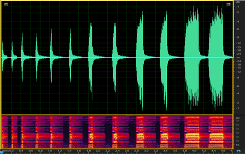
In Equation 1, preferences were evaluated for five types of 5-second Klaxonsounds, which were designed with the Klaxon’s operating time and downtime appropriately adjusted. We performed 100 Mean Option Score (MOS) evaluations of the 5 types of Klaxons three times, then MOS evaluation, and started to listen to the existing Klaxon sounds of three times for 1 second to get the sound criterion. The evaluation items were MOS measurement for risk perception, loudness, unpleasantness, and stress. Results from the evaluation of preference, when designing various forms of the Klaxon sound, noted that giving the horn sound rhythm was preferred compared to the conventional horn sound when continuously heard for 5 seconds. When the rhythm was changed by the sound of Klaxon, the average perceived horn sound level decreased by 20dB. This can be heard in the human ear if the sound is rhythmic rather than normal. Hearing can be perceived as a simple tone, but rhythmic sound can also be perceived easily. In fact, it was found that the sound that when rhythm was added to a sound, it was found to be more pleasant than the corresponding normal sound

horns


1pEAa2 – Rotor noise control using 3D-printed porous materials

Chaoyang Jiang, Yendrew Yauwenas, Jeoffrey Fischer, Danielle Moreau and Con Doolan-c.doolan@unsw.edu.au
School of Mechanical and Manufacturing Engineering
University of New South Wales
Sydney, NSW, Australia, 2052

Popular version of paper 1pEAa2, “Rotor noise control using 3D-printed porous materials”
Presented Monday, December 04, 2017, 1:15-1:30 PM, Balcony N
174th ASA meeting, New Orleans

You may not realise it, but you are surrounded by rotor blades.  Fans in your computer, the air-conditioning system above your head, the wind turbine creating your renewable energy and the jet engines powering you to your next holiday or business meeting are some examples of technology where rotor blades are essential.  Unfortunately, rotor blades create noise and with so many of them, controlling rotor noise is necessary to improve the liveability and health of our communities.

Perhaps the most challenging type of rotor noise to control is turbulent trailing edge noise.  Trailing edge noise is created by turbulence in the air surrounding the rotor blade passing the blade trailing edge. This noise is produced over a wide range of frequencies (it is broadband in nature) because it is the acoustic signature of turbulence, which is a random mixture of swirling eddies of varying size.

Because this noise is driven by turbulence and its interaction with the rotor blade, it is difficult to predict and very challenging to control.  Adding porous material to a rotor blade has been shown to provide some noise relief; however, the amount of noise control is usually small and sometimes more noise is created by the porous material itself.  The problem to solve is to work out how to fabricate a quiet rotor blade with optimised and integrated porosity.  This is a significant departure from current methods, that normally apply standard porous materials late in the design or manufacturing process.

We use 3D printing technology to overcome this problem.  3D printing (also known as additive manufacturing) allows complex designs to be realised quickly through carefully controlled deposition of material (polymer, metal or ceramic).  We have used 3D printing to explore how porosity in polymers can be optimised with subsurface cavities to provide maximum sound absorption over a wide range of frequencies.  Then, we 3D print these porous designs directly into the rotor blade of a fan and test their acoustic performance in a special facility at UNSW Sydney.

Figure 1(a) shows 3D printed rotor blades under test at UNSW Sydney, with a picture of the 3D printed blade tip, with porous trailing edge, shown in figure 1(b).  A three-bladed fan is shown and in the background, a microphone array.  The microphone array allows very accurate noise measurements from the rotor blades.  When we compare solid and 3D printed porous blades, significant noise reduction is achieved, as shown in figure 2.  Over 10 dB of noise control can be achieved, which is much higher than other control methods.  Audio files (see below) allow you to hear the difference between regular solid blades and the 3D printed porous blades.

3D printing has shown that it is possible to produce much quieter rotor blades than we have been able to previously.  Our next step is to further optimise the porosity designs to achieve maximum noise reduction.  We are also investigating the impact of these designs on aerodynamic performance to ensure excessive drag is not produced.  Further, exploring the use of metallic 3D printing systems is required to make more durable rotor blades suitable for extreme environments, such as gas turbine blades.

(a)Rotor noise (b)Rotor noise

Figure 1.  3D rotor blades under test at UNSW Sydney.  (a) Test rig with microphone array; (b) illustration of rotor blade with integrated porosity.

Rotor noise

Figure 2.  Comparison of noise spectra from solid and porous rotor blades at 900 RPM and blade pitch angle of 5 degrees.

Audio 1: Solid rotor blades spinning at 900 RPM

Audio 2: 3D printed porous rotor blades spinning at 900 RPM

2aEA6 – Carbon Nanotube Speakers – Future of Transparent and Lightweight Solid-State Speakers

Suraj M Prabhu – smprabhu@mtu.edu
Dr. Andrew Barnard – arbarnar@mtu.edu
Dynamic Systems Laboratory
R.L. Smith Building, 1400 Townsend Drive
Houghton, MI 49931

Popular Version of paper 2aEA6, “Carbon Nanotube Coaxial Thermophone for Automotive Exhaust Noise Cancellation”
Presented Tuesday morning, November 5, 2017
174th ASA Meeting, New Orleans

Everyday noise affects human health and is a major irritant for people of all ages. Automotive exhaust noise is the one of the most common community noises. Exhaust noise is generated in the engine, travels down the exhaust pipe with the exhaust gases, and is radiated out to the atmosphere. Due to the presence of enormous numbers of automobiles, people are exposed to significant levels of exhaust noise over their lifetime and, so it is important to control the exhaust noise through engineering noise control technology.

The two types of noise control systems used are passive control system and active control systems. Passive control system uses a muffler to attenuate and/or absorb the exhaust noise. An active control system has a loudspeaker that generates a sound with equal amplitude and opposite phase to cancel the exhaust noise. This works just like noise canceling headphones that are used by many air travelers, except it is done at the source.

Carbon nanotubes (CNT) are carbon nano-structures which when stretched form extremely lightweight, flexible films. These films adhere to any conductive surface to form a thermal speaker and when current is passed through them; their surface temperature fluctuates very rapidly. These fluctuations produce pressure waves in the medium near the film, thereby producing sound. The speaker uses no moving parts to produce sound and hence it is solid state in operation.

Figure 1: Automotive exhaust noise schematic

As the operating temperature of CNT speakers is high as compared to the temperature of the exhaust gases, the speakers can be mounted directly onto the tailpipe. The design of the CNT speaker is a coaxial transducer in the form of a co-axial spool. In addition, compared to the other components of the speaker, the CNT film itself is massless and so the overall weight of the speaker is much less compared to traditional loudspeakers with magnets. When tested in the laboratory for noise cancellation, an average cancellation of 12 – 15 dB was achieved across exhaust frequency ranges.   

Figure 2: Passive control system schematic indicating the location of a single muffler along the tailpipe

Figure 3: Active control system schematic indicating the mounting of the loudspeaker at the end of a side branch and the mounting of the entire setup on the tailpipe.

Carbon nanotubes

Figure 4: Planar CNT speaker having the film stretched between two electrodes and attached to an insulating base with electrical connector

Carbon nanotubes

Figure 5: Coaxial CNT speaker (prototype) having two end plates (white discs), electrodes with wires for connection, CNT (black film) wrapped around the electrodes protected from the atmosphere by a transparent cover

1pEAa4 – How does the stethoscope actually work?

Lukasz J. Nowak – lnowak@ippt.pan.pl
Institute of Fundamental Technological Research, Polish Academy of Sciences
Pawinskiego 5B
02-106 Warszawa, Poland

Popular version of paper 1pEAa4, “An Experimental Study on the Role and Function of the Diaphragm in Modern Acoustic Stethoscopes”
Presented Monday afternoon, December 04, 2017, 1:45 PM, Balcony N
174th ASA meeting, New Orleans

Acoustic stethoscope, invented over 200 years ago by French physician, Rene Laennec, is the most commonly used medical diagnostic device and also the symbol of medical professionals. Thus, it might sound surprising, that the physics underlying the operation of this simple, mechanical device is still not well understood. The theory of operation of the stethoscope is widely described in the medical literature. However, most of the presented statements are based on purely intuitive conclusions, subjective impressions or on the results of experiments which do not reflect the complex mechanical problem of the chestpiece – patient interaction. Some recently published findings[1,2] suggest, that the state of the art in the field should be verified.

One of the main challenges in determining acoustic properties of stethoscopes is the fact, that under patient examination conditions (i.e. the only case that actually matters for the considered problem) the chestpiece of the stethoscope is mechanically coupled with a body. The effects of this coupling significantly alter the sought parameters. Thus, you cannot simply replace a patient with a loudspeaker, in order to use harmonic test signals, as in the normal case of measuring acoustic parameters of any standard audio device. You have to perform the analysis and draw the conclusions based on the sounds from the inside of the body of a patient, and those are relatively quiet, noisy, and variable in nature.

The present study focuses on the role and function of the diaphragm in modern acoustic stethoscopes. During auscultation, the diaphragm is excited to vibrate by the underlying body surface, and thus it is the source of sound transmitted through the hollow tubes of a stethoscope to the ears of the physician. The higher are the velocity level values distributed across the surface of the diaphragm, the louder will be the perceived sound. Loudness is a crucial parameter, as the auscultation sounds are very quiet in general, and the diagnosis is often obtained based on the distinction of very subtle changes in those signals. Different stethoscope manufacturers use various materials, shapes, sizes and attaching means for the diaphragms, claiming that specific solutions provide optimal sound parameters. However, no objective data regarding this problem are available, and thus, such statements cannot be accepted from the scientific point of view.

A detailed experimental methodology for determining vibroacoustic properties of different kinds of diaphragms is introduced in the present study. A laser Doppler vibrometer is used to measure the velocity of vibrations of various points on the surface of a diaphragm during heart auscultation (Figure 2). At the same time, an electrocardiography (ECG) signal is also recorded. The ECG signal is used to extract only a subset of clean and uncorrupted velocity signals, without noise and other, interfering body sounds (see Figure 3). The parameters of the extracted and selected fragments are statistically analyzed.

The box plot in Figure 4 shows the values of velocity of vibrations determined at the center and close to the edge for various types of diaphragms encountered in modern acoustic stethoscopes. The first two boxes on the left correspond to the case without a diaphragm. In general, the higher values, and the lower differences between the center and the edge – the better. As it can be seen, the results differ significantly between various diaphragm types. The drawn conclusions are especially important from the physicians’ point of view, as the acoustic efficiency of a stethoscope translates directly into the quality of the diagnosis. An open question remains if and how it could be possible to significantly improve the efficiency of the existing solutions? The analysis of the obtained results states a good foundation for further investigations in this direction, as it allows to better understand the phenomena underlying auscultation examination and to formulate some general assumptions regarding the most promising solutions.

stethoscope
Figure 1. A modern acoustic stethoscope with a diaphragm chestpiece

 
Figure 2. The laboratory stand used for experimental investigations on the vibroacoustic parameters of various kinds of stethoscope diaphragms

 
Figure 3. All the vibration velocity signals extracted from a single recording, including noisy and corrupted ones (top), and the corresponding subset of signals selected for further analysis (bottom)


Figure 4. Box plot presenting the distribution of the measured velocity of vibrations values at the center and edge points for each of the considered cases

[1] Nowak, L. J., and Nowak, K. M. (2017). “Acoustic characterization of stethoscopes using auscultation sounds as test signals,” J. Acoust. Soc. Am., 141, 1940–1946. doi:10.1121/1.4978524

[2] Nowak, K. M., and Nowak, L. J. (2017). “Experimental validation of the tuneable diaphragm effect in modern acoustic stethoscopes,” Postgrad. Med. J., , doi: 10.1136/postgradmedj-2017-134810. doi:10.1136/postgradmedj-2017-134810

4aEA1 – Aero-Acoustic Noise and Control Lab

Aero-Acoustic Noise and Control Lab – Seoryong Park – tjfyd11@snu.ac.kr

School of Mechanical and Aerospace Eng., Seoul National University
301-1214, 1 Gwanak-ro, Gwanak-gu, Seoul 151-742, Republic of Korea

Popular version of paper 4aEA1, “Integrated simulation model for prediction of acoustic environment of launch vehicle”
Presented Thursday morning, December 1, 2016
172nd ASA Meeting, Honolulu

Literally speaking, a “sound” refers to a pressure fluctuation of the air. This means, for example, the sound of a bus passing means our ear senses the pressure fluctuation or pressure variation the bus created. During our daily lives, there are rarely significant pressure fluctuations in the air above common noises, but in special cases it happens. Windows are commonly featured in movies breaking from someone screaming loudly or in high pitches in the movie. This is usually exaggerated, but not out of the realm of what is physically possible.

The pressure fluctuations in the air caused by sound can cause engineering problems for loud structures such as rockets, especially given that the pressure nature of the sounds waves that means louder sounds result from larger pressure fluctuations and can cause more damage. Rocket launches are particularly loud and the resulting pressure change in the air can affect the surface of the launched vehicle as the form of the force shown as Figure 1.

fig-1-the-magnitude-of-acoustic-loads-on-the-luanch-vehicle
Figure 1. The Magnitude of Acoustic Loads on the Launch Vehicle

fig-2-acoustic-loads-generated-during-a-lift-off
As the vehicle is launched (Figure. 2), it reaches volumes over 180dB, which corresponds to about 20,000 Pascals in pressure change. This pressure change is about 20% of atmospheric pressure, which is considered very large. Because of the pressure change during launching, communication equipment and antenna panel can incur damage, causing the malfunctioning of the fairing, the protective cone covering the satellite. In the engineering field, the load created by the launching noise is called acoustic load, and many studies are in progress related to acoustic load.

Studies focused on the relationship between a launching vehicle and its acoustic load is categorized, to rocket engineers, under “prediction and control.” Prediction is divided into two aspects: internal acoustic load; and external acoustic load. Internal acoustic load refers to sound delivered from outside to inside, while external acoustic load is the noise directly from the jet fire. There are two ways to predict the external acoustic load, namely an empirical method and numerical method. The empirical method was developed by NASA in 1972 and uses the collected information from various studies. The numerical method employs mathematical formulas related to noise and electric wave calculated using computer modeling. As computers become more powerful, this method continues to gain favor. However, because numerical methods require so much calculation time, they often require the use of dedicated computing centers. Our team instead focused on using the more efficient and faster empirical method. fig-3-external-acoustic-loads-prediction-result-%28spectrum%29

Figure 3 shows the results of our calculations, depicting the expected sound spectrum. We can consider various physics principles involved during a lift-off, such as sound reflection, diffraction and impingement that could affect the original empirical method results.

Meanwhile, our team used a statistical energy analysis method to predict the internal acoustic load caused by the predicted external acoustic load. This method is used often to predict internal noise environments. It is used to predict the internal noise of a launching vehicle as well as aircraft and automobile noise. Our research team used a program called, VA One SEA, for predicting these noise effects, shown as figure. 4.

fig-4-modeling-of-the-payloads-and-forcing-of-the-external-acoustic-loads
Figure 4. Modeling of the Payloads and Forcing of the External Acoustic Loads

After predicting internal acoustic load, we decreased the acoustic load to conduct an internal noise control study. A common way to do this is by sticking noise-reducing material to the structure. However, the extra weight from the noise-reducing material can cause decreased performance. To overcome this side effect, we also conducted a study about active noise control, which is in progress. Active noise control refers to reducing the noise by making antiphase waves of the sound for cancelling. Figure 5 shows the experimental results of applied SISO Noise Control, showing the reduction of noise is significant, especially for low frequencies.

fig-5-experimental-results-of-siso-active-noise-control
Figure 5. Experimental Results of SISO Active Noise Control

Our research team applied the acoustic load prediction method and control method to the Korean launching vehicle, KSR-111. Through this application, we developed an improved empirical prediction method that is more accurate than previous methods, and we found usefulness of the noise control as we established the best algorithm for our experimental facilities and the active noise control area.

4pEA7 – Acoustic Cloaking Using the Principles of Active Noise Cancellation

Jordan Cheer – j.cheer@soton.ac.uk
Institute of Sound and Vibration Research
University of Southampton
Southampton, UK 

Popular version of paper 4pEA7, “Cancellation, reproduction and cloaking using sound field control”
Presented Thursday morning, December 1, 2016
172nd ASA Meeting, Honolulu

Loudspeakers are synonymous with audio reproduction and are widely used to play sounds people want to hear. Loudspeakers have also been used for the opposite purpose, to attenuate noise that people may not want to hear. Active noise cancellation technology is an example of this, which combines loudspeakers, microphones and digital signal processing to adaptively control unwanted noise sources [1].

More recently, the scientific community has focused attention on controlling and manipulating sound fields to acoustically cloak objects, with the aim of rendering objects acoustically invisible. A new class of engineered materials called metamaterials have already demonstrated this ability [2]. However, acoustic cloaking has also been demonstrated using methods based on both sound field reproduction and active noise cancellation [3]. Despite its demonstration there has been limited research exploring the physical links between acoustic cloaking, active noise cancellation and sound field reproduction. Therefore, we began exploring these links with the aim of developing active acoustic cloaking systems that build on the advanced knowledge of implementing both audio reproduction and active noise cancellation systems.

Acoustic cloaking attempts to control the sound scattered from a solid object. Using a numerical computer simulation, we therefore investigated the physical limits on active acoustic cloaking in the presence of a rigid scattering sphere. The scattering sphere, shown in Figure 1, was surrounded by an array of sources (loudspeakers) used to control the sound field, shown by the black dots surrounding the sphere in the figure. In the first instance we investigated the effect of the scattering sphere on a simple sound field.

Looking at a horizontal slice through the simulated sound field without a scattering object, shown in the second figure, modifications by the presence of the scattering sphere are obvious in comparison to the same slice when the object is present, seen in third figure. Scattering from the sphere distorts the sound field, rendering it acoustically visible.

figure1 - Acoustic Cloaking

Figure 1 – The geometry of the rigid scattering sphere and the array of sources, or loudspeakers used to control the sound field (black dots).

figure2 - Acoustic Cloaking

Figure 2 – The sound field due to an acoustic plane wave in the free field (without scattering).

figure3 - Acoustic Cloaking

Figure 3 – The sound field produced when an acoustic plane wave is incident on the rigid scattering sphere.

figure4 - Acoustic Cloaking

Figure 4 – The sound field produced when active acoustic cloaking is used to attempt to cancel the sound field scattered by a rigid scattering sphere and thus render the scattering sphere  acoustically ‘invisible’.

To understand the physical limitations on controlling this sound field, and thus implementing an active acoustic cloak, we investigated the ability of the array of loudspeakers surrounding the scattering sphere to achieve acoustic cloaking [4]. In comparison to active noise cancellation, rather than attempting to cancel the total sound field, we only attempted to control the scattered component of the sound field and thus render the sphere acoustically invisible.

With active acoustic cloaking, the sound field appears undisturbed, where the scattered component has been significantly attenuated and results in a field, shown in the fourth figure, that is indistinguishable from the object-less simulation of the Figure 2.

Our results indicate active acoustic attenuation can be achieved using an array of loudspeakers surrounding a sphere that would otherwise scatter sound detectably. In this and related work[4], further investigations showed that the performance of active acoustic cloaking is most effective when the loudspeakers are in close proximity to the object being cloaked. This may lead to design concepts involving acoustic sources embedded in objects for acoustic cloaking or control of the scattered sound field.

Future work will attempt to demonstrate the performance of active acoustic cloaking experimentally and overcome significant challenges of not only controlling the scattered sound field, but detecting it using an array of microphones.

[1]   P. Nelson and S. J. Elliott, Active Control of Sound, 436 (Academic Press, London) (1992).

[2]   L. Zigoneanu, B.I. Popa, and S.A. Cummer, “Three-dimensional broadband omnidirectional acoustic ground cloak”. Nat. Mater, 13(4), 352-355, (2014).

[3]   E. Friot and C. Bordier, “Real-time active suppression of scattered acoustic radiation”, J. Sound Vib., 278, 563–580 (2004).

[4]   J. Cheer, “Active control of scattered acoustic fields: Cancellation, reproduction and cloaking”, J. Acoust. Soc. Am., 140 (3), 1502-1512 (2016).