4aPPa4 – Perception of Vowels and Consonants in Cochlear Implant Users

Melissa Malinasky – Melissa_Malinasky@rush.edu

Popular version of paper 4aPPa4
Presented Thursday morning, December 10 , 2020
179th ASA Meeting, Acoustics Virtually Everywhere

Understanding individual phoneme sounds is vital to speech perception. While cochlear implants (CI) can improve speech understanding, they also introduce distortions to sound input due to the limits of technology versus the human ear. Understanding which phonemes are most commonly misunderstood, and in what context this occurs can lead to the development of better signal processing strategies in Cis and better audiologic rehabilitation strategies post-implantation. The objective of this study was to evaluate perceptual differences in accuracy of specific vowels and consonants in experienced CI users. This study looked at 25 experienced adult CI users that were a part of a larger study by Shafiro et al. Participants were presented with a word, and given closed-set responses that tested their ability to distinguish between individual consonants of vowels. To determine if they can make these distinctions, each multiple-choice response was varied by one phonemic sound (i.e. bad vs bat, hud vs hid).

Cochlear implant users achieved 78% accuracy overall for consonant sounds compared to 97% for normal hearing participants. This shows that CI users are quite successful at identifying individual consonants sounds. Consonants at the beginning of the word were identified with 80.5% accuracy, while consonants at the end of the word were identified with 75.4% accuracy. This is not as great of a variation as we would have predicted.

For correct identification of vowels, cochlear implant users had 75% accuracy, while normal hearing users had 92% accuracy. Vowels were analyzed based on accuracy, as well as other vowels they were confused with. Some vowel sounds had over 80% accuracy, while others had as low as 45%.

Overall, this study shows that CI users have fairly good consonant and vowel recognition. These results are consistent with what has been previously reported by Rodvik et al. (2018). While CI users do perform quite well, they are still outperformed by their normal hearing, age-matched peers. The presence of a single consonant can affect someone’s entire understanding of a word, and it is important to understand where the most difficulty lies for CI users. Improvement in identification of some of these more difficult consonants can give this population greater access to language understanding. These findings can also help tailor auditory training programs, and help improve speech intelligibility in CI users.

References:

Hillenbrand, J., Getty, L. A., Clark, M. J., & Wheeler, K. (1995). Acoustic characteristics of American English vowels. The Journal of the Acoustical Society of America, 97(5), 3099–3111. doi: 10.1121/1.411872

House, A. S., Williams, C. E., Hecker, M. H. L., & Kryter, K. D. (1965). Articulation testing methods: Consonantal differentiation with a closer response set. The Journal of the Acoustical Society of America, 37(1), 158–166. https://doi.org/10.1121/1.1909295

Peterson, G. E., & Barney, H. L. (1952). Control Methods Used in a Study of the Vowels. The Journal of the Acoustical Society of America, 24(2), 175–184. doi: 10.1121/1.1906875

Rødvik AK, von Koss Torkildsen J, Wie OB, Storaker MA, Silvola JT. Consonant and Vowel Identification in Cochlear Implant Users Measured by Nonsense Words: A Systematic Review and Meta-Analysis. J Speech Lang Hear Res. 2018 Apr 17;61(4):1023-1050. doi: 10.1044/2018_JSLHR-H-16-0463. PMID: 29623340.

Shafiro V, Hebb M, Walker C, Oh J, Hsiao Y, Brown K, Sheft S, Li Y, Vasil K, Moberly AC. Development of the Basic Auditory Skills Evaluation Battery for Online Testing of Cochlear Implant Listeners. Am J Audiol. 2020 Sep 18;29(3S):577-590. doi: 10.1044/2020_AJA-19-00083. Epub 2020 Sep 18. PMID: 32946250.

1aBAd2 – Pilot studies on zebrafish echocardiography and zebrafish ultrasound vibro-elastography

Xiaoming Zhang, PhD –Zhang.Xiaoming@mayo.edu
Department of Radiology
Mayo Clinic
Rochester, MN 55905

Alex X. Zhang, Xiaolei Xu, PhD
Department of Biochemistry and Molecular Biology
Mayo Clinic
Rochester, MN 55905

Popular version of paper 1aBAd2
Presented Monday morning, December 7, 2020
179th ASA Meeting, Acoustics Virtually Everywhere

Zebrafish are increasingly being used as animal models for human diseases such as cardiomyopathy and neuroblastoma.  Like humans, zebrafish have a near-fully sequenced genome. However, the body of a zebrafish is only about 1.5-2.5 cm in length, which is much smaller than a person. To extrapolate results from zebrafish to humans, reliable quantitative measures on zebrafish are needed.

In this pilot study, we develop two noninvasive measurement techniques in zebrafish. One is to measure the heart function of zebrafish using echocardiography. Another is to measure the elastic property of zebrafish tissues using ultrasound vibro-elastography.

In zebrafish echocardiography, an adult zebrafish was anesthetized for three minutes in a tricaine solution. The zebrafish was then taken out of the anesthetic solution and positioned in a specially designed holder. The high-frequency Vevo 3100 ultrasound system with a MX700 ultrasound probe (29-71 MHz) was used to measure the heart function of the zebrafish. Figure 1 shows the experimental setup. Ultrasound imaging was used to measure heart volumes at the end of systole and diastole. The ejection fraction of the heart was analyzed. Pulse-wave Doppler was also used to analyze the heart function. We developed a technique to improve zebrafish echocardiography by removing the surface skin tissue near the heart of a zebrafish, which significantly improved the resolution of ultrasound images for analyzing heart function in zebrafish. All zebrafish recovered from this procedure and the subsequent echocardiography exam.

Another pilot study was to measure the elastic properties of zebrafish using ultrasound vibro-elastography. A 0.1 second gentle harmonic vibration was generated on the tail of a zebrafish using a sphere tip indenter with a 3 mm diameter. Shear wave propagation in the zebrafish was measured using another ultrasound system with a high frequency 18 MHz ultrasound probe. High frame rate ultrasound images were obtained using this ultrasound system to measure the generated wave propagation (300-500 Hz) in the bodies of the zebrafish. Figure 2 shows the experimental setup. Video 1 shows the wave propagation in a zebrafish. A region of interested (ROI) was used to analyze the sheer wave speed map. The ROI covered the most central area of the zebrafish surrounding the heart. The wave speed was 3.13 ± 1.20 (m/s) in the ROI at 300 Hz. It was found that wave speed increased from 300 Hz to 500 Hz as it passed through the zebrafish. All zebrafish recovered from this experiment. We will improve this technique for measuring elastic properties of the heart of zebrafish. It is feasible to develop this technique for measuring the elastic properties of zebrafish for phenotyping various diseases.

zebrafish echocardiography
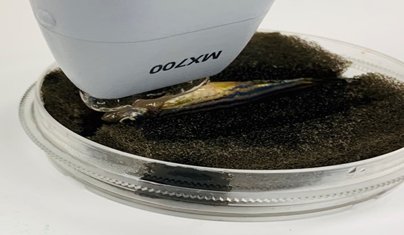
Figure 1. Experiment setup of zebrafish echocardiography.

zebrafish ultrasound vibro-elastographyFigure 2. Experimental setup of zebrafish ultrasound vibro-elastography.

5pAAa4 – The clapping circle “squeak,” finally explained

“The clapping circle “squeak,” finally explained”

Elspeth Wing – winge@purdue.edu
Steven Herr – sherr@purdue.edu
Alexander Petty – petty14@purdue.edu
Alexander Dufour – adufour@purdue.edu
Frederick Hoham – fhoham@purdue.edu
Morgan Merrill – mmerril@purdue.edu
Donovan Samphier – dsamphie@purdue.edu
Weimin Thor – wthor@purdue.edu
Kushagra Singh – singh500@purdue.edu
Yutong Xue – xyt@alumni.purdue.edu
Davin Huston – dhhustion@purdue.edu
Stuart Bolton – bolton@purdue.edu

Purdue University
610 Purdue Mall
West Lafayette, IN 47907

Popular version of paper 5pAAa4 (your paper version)
Presented Friday morning, December 11, 2020
179th ASA Meeting, Acoustics Virtually Everywhere

Ask any member of the Purdue University community about the “Clapping Circle,” and they will eagerly tell you about the unforgettable squeak that appears to materialize out of thin air when you stand in the middle of it and clap your hands. In 2019, the Purdue student chapter of the Acoustical Society of America gathered a team of undergraduate students, graduate students, and faculty to conduct a study to establish, once and for all, the specific acoustic mechanisms behind “the squeak.”

An aerial photo of the Clapping Circle

An aerial photo of the Clapping Circle


A recording of the clap and subsequent squeak

The Clapping Circle is a circular plaza consisting of sixty-six concentric rings of stone tiles, and with stone benches on its edges. This architectural feature has led to numerous theories from acoustics experts about the cause: from reflections off the ground tiles, to the surrounding benches, or even the surrounding trees and buildings.

The members of the Purdue student chapter of the ASA decided to thoroughly investigate. They set up a multidirectional speaker in the middle to simulate a clap at different heights, and then recorded the results through a microphone. They even covered the entire circle in moving blankets to act as a control.

A photograph of the speaker and microphone in the middle of the circle during testing

A photograph of the speaker and microphone in the middle of the circle during testing

The experiments confirmed their theory: two phenomena known as “acoustical diffraction grating” and “repetition pitch”  combined to create the effect.  Acoustical diffraction grating refers to the reinforcement of certain frequencies produced by a reflection, which they theorized was coming from the progressively more distant bevels between the ground tiles. “Repetition pitch” refers to the ear’s processing of repeated percussive sounds as a pitch. Put both of these together, and you get a rapidly descending pitch which sounds like a squeak.

When they covered the circle with hundreds of moving blankets, the squeak disappeared – ultimately proving their theory correct.

While similar studies have been performed at stepped architectural features (such as the pyramid at Chichen-Itza), this is the most completely researched explanation of the “clapping circle” phenomenon.  And now, thanks to these diligent acoustics students, the tour guides at Purdue University will have a proper scientific explanation for “the squeak!”

Some of the investigation team at the site

Check out the video link below to a promotional video about the project created by Purdue University

Video: https://www.youtube.com/watch?v=Cuv1Pd_hS_I

More information: https://www.purdue.edu/newsroom/stories/2020/Stories%20at%20Purdue/explaining-the-sound-of-purdues-clapping-circle.html

1aSC3 – Acoustic changes of speech during the later years of life

Benjamin Tucker – benjamin.tucker@ualberta.ca
Stephanie Hedges – shedges@ualberta.ca
Department of Linguistics
University of Alberta
Edmonton, Alberta T6G 2E7
Canada

Mark Berardi – mberardi@msu.edu
Eric Hunter – ejhunter@msu.edu
Department of Communicative Sciences and Disorders
Michigan State University
East Lansing, Michigan 48824

Popular version of paper 1aSC3 (your paper version)
Presented Monday morning 11:15 AM – 12:00P PM, December 7, 2020
179th ASA Meeting, Acoustics Virtually Everywhere

Research into the perception and production of the human voice has shown that the human voice changes with age (e.g., Harnsberger et al., 2008). Most of the previous studies have investigated speech changes over time using groups of people of different ages, while a few studies have tracked how an individual speaker’s voice changes over time. The present study investigates three male speakers and how their voices change over the last 30 to 50 years of their lives.

We used publicly available archives of speeches given to large audiences on a semi-regular basis (generally with a couple of years between each instance). The group of speeches was given during the last 30-50 years of each speaker’s life, meaning that we have samples ranging from the speakers’ late 40s to early 90s. We extracted 5-minute samples (recordings and transcripts) from each speech. We then used the Penn forced-alignment system (this system finds and marks the boundaries of individual speech sounds) to identify word and sound boundaries. Acoustic characteristics of the speech were extracted from the speech signal using a custom script using the Praat software package.

In the present analysis, we investigate changes in the vowel space (the acoustic range of vowels a speaker has produced), fundamental frequency (what a listener hears as pitch), the duration of words and sounds (segments), and speech rate. We model the acoustic characteristics of our speakers using Generalized Additive Models (Hastie & Tibshirani, 1990), which allows for an investigation of non-linear changes over time.

The results are discussed in terms of vocal changes over the lifespan in the speakers’ later-years. Figure 1 illustrates the change in one speaker’s vowel space as he ages. We find that for this speaker the vowel space shifts to lower frequencies as he ages.

Figure 1 – An animation of Speaker 1’s vowel space and how it changes over a period of 50 years. Each colored circle represents a different decade.

We also find a similar effect for fundamental frequency across all three speakers, Figure 2, where the average fundamental frequency of their voices gets lower and lower as they age and then starts to get higher after the age of 70. This effect is the same for word and segment duration. We find that on average as our three speakers age their speech (at least when giving public speeches) gets faster and then slows down after around the age of 70.

Figure 2: Average fundamental frequency of our speakers’ speech as they age.

Figure 3: Average speech rate in syllables per second of our speakers’ speech as they age.

While on average our three speakers show a change in the progression of their speech at the age of 70, each speaker has their own unique speech trajectory. From a physiological standpoint, our data suggest that with age come not only laryngeal changes (changes to the voice) but also a decrease in respiratory health – especially expiratory volume – as has been reflected in previous studies.

2pUWb2 – Study of low frequency flight recorder detection

I Yun Su – r07525010@ntu.edu.tw
Wen-Yang Liu – r06525035@ntu.edu.tw
Chi-Fang Chen – chifang@ntu.edu.tw
Engineering Science and Ocean Engineering,
National Taiwan University,
No. 1 Roosevelt Road Sec.#4
Taipei City, Taiwan

Li-Chang Chuang – eric@ttsb.gov.tw
Kai-Hong Fang – khfang@ttsb.gov.tw
Taiwan Transportation Safety Board
11th Floor, 200, Section 3,
Beixin Road, Xindian District,
New Taipei City, Taiwan

Popular version of paper 2pUWb2
Presented Tuesday afternoon, December 8, 2020
179th ASA Meeting, Acoustics Virtually Everywhere

A flight recorder is installed in every aircraft to record the flight status. When the aviation accident occurs, this recorder can help clarify the cause of the incident. Furthermore, if the plane crashes into the ocean, the underwater locater beacon (ULB) inside the flight recorder will be triggered which would make a sound that could be located by the rescue team.

In 2009, there was a serious accident involving the Air French flight 447. According to the final report, French Civil Aviation Safety Investigation Authority suggested that the ULB should acquire extended transmission time up to 90 days and increased transmission range. In Taiwan, the flight recorder has already been installed with a 37.5 kHz ULB inside the tail section of every vehicle, and now Taiwan Transportation Safety Board considered to put in an additional 8.8 kHz ULB in the flight belly. (Picture 1)

underwater locater beacon (ULB) inside the flight recorder

Picture 1: The positions of the 37.5 kHz and 8.8 kHz ULB on the plane.

The main propose of this study is to understand the performance of the newly bought 8.8 kHz ULB – DUKANE SEACOM DK180. Firsts off, I did the simulation on both ULB to compare the detection ranges (DR), and according to the beacon specifications, the source level (SL) of the both is 160 dB re 1μPa.

For the DR to be simulated, the transmission loss (TL) which is affected by a lot of different environmental parameters must be determined first. This study is based on the Taiwan database, and using the Gaussian beam propagation to calculate the TL. After the TL is acquired, the noise level (NL) which also has certain impact on the DR has to be determined. Generally, the lower the frequency, the longer the DR. DR can be determined by passive sonar equation, and can be derive the FOM = SL – NL – DT. The DT is Detection Threshold and the FOM is Figure of Merit, which is the maximum TL that can detect. The intersection of the TL and FOM is DR. In the study, the DT is set to be zero. At the Point A, the NL of the 8.8 kHz is 78 dB re 1μPa and for 37.5 kHz is 65 dB re 1μPa, so the FOM of the 8.8 kHz is 82 dB re 1μPa and for 37.5 kHz is 95 dB re 1μPa. The DR in 8.8 kHz ULB is about twice than 37.5 kHz ULB at Point A. (Picture 2)

Picture 2: Detection Ranges of 8.8 kHz ULB and 37.5 kHz ULB in the Point A.

In the study, I have also done the experiment in Taiwan Miaoli offshore. The results also show that the newly bought 8.8 kHz ULB would have a smaller TL and longer DR. In summary, with an additional 8.8 ULB, the more precise prediction of the beacon location could be obtained.

2pBAc – Targeting Sound with Ultrasound in the Brain

Scott Schoen Jr – scottschoenjr@gatech.edu
Costas Arvanitis – costas.arvanitis@gatech.edu

Georgia Tech
901 Atlantic Dr
Atlanta, GA 30318

Popular version of 2pBAc – Spatial Characterization of High Intensity Focused Ultrasound Fields in the Brain
Presented Tuesday afternoon, December 8, 2020
179th ASA Meeting, Acoustics Virtually Everywhere

The pitch and size of a sound are quite intrinsically connected. This is why, for instance, low-register instruments (such as a tuba or double bass) are large, while higher pitched ones may be very small (like a piccolo or triangle). Sound travels in waves, and the product of the length of the wave (wavelength) and its pitch (frequency) is a constant (namely, the speed of sound).

Consequently, the wavelength of sounds we can hear may be between about 15 m and 0.2 cm. But just as there are wavelengths of light we cannot see (such as ultraviolet and X-rays), there exists sound with much smaller wavelengths. Ultrasound, so called since its frequency is above our hearing range, is able to travel through human tissue and enables noninvasive imaging with millimeter resolution.

Since sound is pressure, it also carries energy. And, much like sunlight through a magnifying glass, sound energy may be focused to a small area to cause heating. This technique has allowed noninvasive and minimally invasive therapy, where focused ultrasound (FUS) creates small regions of high heat or forces to burn or manipulate the tissue. This is especially important for brain diseases, where surgery is particularly challenging.

ultrasound
Fig. 1 – Human cells are sensitive to sound frequencies from about 20 Hz to 20 kHz (left). However, focusing sound to a small area requires small wavelengths—and thus much higher frequencies (right). Not to Scale

Interestingly, it turns out that at very high pressures, so-called nonlinear acoustic effects become important, and the sound begins to interact with itself. One consequence is that if the FUS has to very high frequencies, say 995 kHz and 1005 kHz, the focal spot will a few millimeters, similar to 1 mm. However, the high pressure interaction will also generate energy at 1005 kHz – 995 kHz = 10 kHz—within the audible and tactile range.

This work describes our use of simulations and experiments to understand how this low frequency energy might be realized for FUS through the skull. Understanding the strength and distribution of low frequency energy generated with high frequency FUS may open a new range of therapeutic and diagnostic capabilities in one of the most complex and medically imperative organs: the brain.